Hello,
As you've seen here a few years ago I'm working on a custom date back for film cameras.
In theory it should have been easy :
1) When the camera takes a pictures it sends a signal by closing a circuit (via the sync cord or the flash mount) for a few milliseconds
2) At the other end, my date back imprints the date when it receives said signal (a circuit is closed)
The problem is, the signal my camera sends is to fast to be catched by the date back.
So for the past 2 years I've been trying to slow down the signal...
- First with a timer 555 and a capacitor.
- Then with an ESP32 and a battery but it was bulky and the battery didn't last long.
- Now I'm using a PIC12F1572 microcontroller powered by the same button cell as the date back (2xLR44)
The code is here : https://pastebin.com/x9jcmzLq
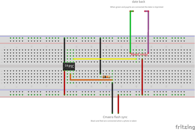
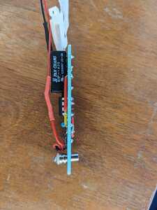
My circuit looks like this :
It has 2 main drawbacks :
1) It outputs 3v inside the camera via the sync cord in order to listen for the signal, i'm afraid it can damage the camera and I have no idea how to avoid this.
2) I need to use a reed relay to avoid sending 3v inside the date back when we just one to close the circuit. I want to keep thing compact and these relays are bigger than the PIC...
Do you have any suggestions on how to avoid leaking voltage inside the camera and the date back without using relays ? Maybe with transistors (I've never used them yet) ? I've also read about "open-drain" and "open-collector" configurations however I don't know how to use it and if it can solve my issues.
Or even better, an easy way to slow down the signal ?
Thanks a lot 🙂
@nicolas Hopefully someone who knows more about circuit design can help you, but I can tell you it's not about slowing things down, you just need a circuit that once triggered will remain 'latched' until whatever work that needs to be done is done. Maybe opto isolators can help, a logic mosfet perhaps or a transistor circuit of some sort.
I am a little unsure why you are concerned about a paltry 3V inside the camera, IIRC, those flash sync circuits used something like 550V. But even though I was late to the digital photography game, the last film camera I used was several decades ago.
There is not enough info here for me to be of much help, but if you can get out of problem solving mode and simply explain what is needed maybe someone can help.
EDIT:
Sorry, if I read your original post correctly, it worked at speeds less than or equal to 1/125 sec, is that right?
For mechanical cameras of that time, that was the fastest shutter speed supported. The mechanical shutter dial blocks the signal at speeds higher than that IIRC.
So for flash sync (1/125) speeds, I think you have already done that, it's just a matter of connecting the wires, no code needed. Speeds faster are not possible.
In order to get the date imprinted at all speeds, a seperate switch is needed. You should consider a tiny switch on the back that you press before taking the picture. That tiny switch turns on the date module for some small amount of time (using a timer IC), I would guess 2 secs.
First computer 1959. Retired from my own computer company 2004.
Hardware - Expert in 1401, and 360, fairly knowledge in PC plus numerous MPU's and MCU's
Major Languages - Machine language, 360 Macro Assembler, Intel Assembler, PL/I and PL1, Pascal, Basic, C plus numerous job control and scripting languages.
My personal scorecard is now 1 PC hardware fix (circa 1982), 1 open source fix (at age 82), and 2 zero day bugs in a major OS.
@nicolas I found the specs of the camera. There is NO signal at shutter speeds faster than 1/125 sec. You will either need to perform major surgery on the camera to have the shutter release switch fire the date module, OR what I would do is add a tiny switch to manually fire the date module with a timer to shut it off after a short time (about 2 secs)
I just thought of a 3rd method. After the picture is taken, use a switch with a timer to give the date module proper exposure (changes with ISO?)
So your picture taking process is the same with the addition of pressing a tiny switch after taking the picture. It may be possible to 'listen' for the shutter release but that at least involves a sensor that needs to fit inside the camera body as well as an MCU or PIC plus a battery, but the later could be outside if you drill a small hole to run the sensor wires into the camera.
First computer 1959. Retired from my own computer company 2004.
Hardware - Expert in 1401, and 360, fairly knowledge in PC plus numerous MPU's and MCU's
Major Languages - Machine language, 360 Macro Assembler, Intel Assembler, PL/I and PL1, Pascal, Basic, C plus numerous job control and scripting languages.
My personal scorecard is now 1 PC hardware fix (circa 1982), 1 open source fix (at age 82), and 2 zero day bugs in a major OS.
Hi @nicolas,
I suspect a simple 'open drain' circuit, typically containing a FET and a resistor, will do nicely for your application, but as you have already realised, such a circuit is not 'floating' in the way relay contacts are isolated from the drive coil, so you need to know the exact circuit of the camera, including battery, switch, backlight, etc. It should be possible to use your multimeter to figure it out.
If you can post a sketch of the circuit ... a legible pen and paper one is fine ... I may be able to help you further.
Best wishes, Dave
Hello, thank you for your answer, sorry for replying late
Hey @zander thank you for your messages,
I am a little unsure why you are concerned about a paltry 3V inside the camera, IIRC, those flash sync circuits used something like 550V
Oh really ? I didn't know that, so no risks of damaging the camera with 3v 🙂
In order to get the date imprinted at all speeds, a seperate switch is needed. You should consider a tiny switch on the back that you press before taking the picture. That tiny switch turns on the date module for some small amount of time (using a timer IC), I would guess 2 secs.
Yes, by just wiring the cables together I get it working for speed slower than 1/125. But I want it to work for all speeds. As this is a challenge to myself and a way to start learning electronics I don't want to use a physical button in order to trigger the date imprint.
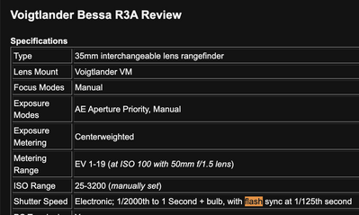
I found the specs of the camera. There is NO signal at shutter speeds faster than 1/125 sec.
There is a signal at all speeds. The 1/125 info you found in the documentation is just the fastest speed you can use with a flash without having the image partial cropped by the shutter curtain, but that's not a limitation for my usecase.
I've already been able to make it work at all speeds with the PIC and the reed relay, I'm just looking for a way to make it more compact/effecient.
@davee Thanks !
Can you confirm I understand you well? I could use an open-drain circuit, but it will "leak" some voltage inside the camera and the date back ? So I need to disassemble the camera to make sure it would be safe ?
If you can post a sketch of the circuit ... a legible pen and paper one is fine ... I may be able to help you further.
Which circuit are you talking about ? The one I already made the PIC microcontroller ?
Thanks
Hi @nicolas,
With respect to my post and your reply:
It is not a case of 'voltage leaking', but rather the need to bring two circuits into 'mutual harmony'. In practice, this flowery phrase might only mean something like picking the right point to add a joining wire or two, but once I know the full details, it will be easier to explain, and hopefully also easier for you to understand what is going on.
The circuit I am mainly concerned is that of the camera itself, which should include showing how your microcontroller circuit is connected to it. Thus, the circuit will include all batteries, switches (e.g. shutter switch), light bulbs, etc. that are involved.
In reality, much of the circuit will probably resemble that of a simple torch (flashlight) with tungsten filament bulb, consisting of switch, battery, and bulb, which seems trivial, but because you want to directly connect your microcontroller circuit, things like battery polarity and voltage, and which side of a battery is being switched become in important, whilst in a simple torch the components can be swapped around and even connected 'backwards' without changing the functionality.
So it is a small amount of vital detail, that needs to be presented accurately.
I hope that is clearer.
Best wishes, Dave
@nicolas This is good news
I've already been able to make it work at all speeds with the PIC and the reed relay, I'm just looking for a way to make it more compact/effecient.
I totally missed the fact it is working. The way to make it smaller then is to substitute a logic level mosfet or possibly some sort of transistor using the smallest SMD parts for the reed relay and similarly for the pic. My hunch is this would be a pcb board no more than 2mm x 2mm based on the 01005 package size which is 0.4mm x 0.2mm. Since this circuit is just a trigger there is no significant amount of power, the LEDs that do the imprinting are seperate.
I don't have a mental picture of the physical size of the data back, but I would look for an opportunity to hot glue in the module. I have used that technique a few times, it waterproofs the device, it acts as strain relief and is electrically non-conductive.
One other option is to build a small box, then attach it to the camera strap and connect the two parts using that super flexible type of wiring.
First computer 1959. Retired from my own computer company 2004.
Hardware - Expert in 1401, and 360, fairly knowledge in PC plus numerous MPU's and MCU's
Major Languages - Machine language, 360 Macro Assembler, Intel Assembler, PL/I and PL1, Pascal, Basic, C plus numerous job control and scripting languages.
My personal scorecard is now 1 PC hardware fix (circa 1982), 1 open source fix (at age 82), and 2 zero day bugs in a major OS.
Hello,
Sorry for the reply, I've been very busy these past weeks.
@davee
I'm afraid of disassembling the camera in order to inspect the circuitry, it's pretty "modern" camera with a lot of electronics inside (lightmeter, shutter, ...)
I'm also not sure I would be capable of extracting any valuable information.
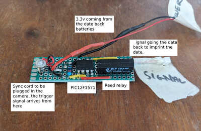
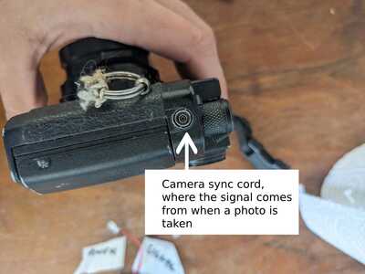
Find schematics and photos of my setup at the end of the post.
@zander
I haven't been able to find SMD relays, do you have a link ? with SMD relays it would become very compact. Indeed my plan would be to hot glue it. Or ideally (if compact enough) to wrap everything in shrinkable sleeve in the middle of the cable going from the camera to the date back.
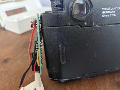
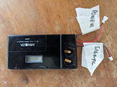
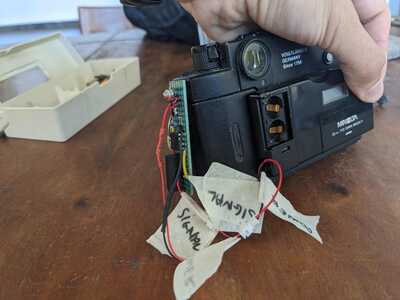
Here are some photos of my setup
Schematics :
Global view
Camera sync cord socket
Circuit with visible sync cord
Circuit connected to camera
Date back with power output (to power the circuit) and signal input to print the date when a photo is taken
Camera + circuit + date back all together
Thanks 🙂
@nicolas You should be able to replace all of that with a single MOSFET, maybe even a tiny surface mount so that it can be shrink wrapped and mounted 'in-line' if you get my meaning. Just determine if the synch signal is a grounding, or a positive voltage.
First computer 1959. Retired from my own computer company 2004.
Hardware - Expert in 1401, and 360, fairly knowledge in PC plus numerous MPU's and MCU's
Major Languages - Machine language, 360 Macro Assembler, Intel Assembler, PL/I and PL1, Pascal, Basic, C plus numerous job control and scripting languages.
My personal scorecard is now 1 PC hardware fix (circa 1982), 1 open source fix (at age 82), and 2 zero day bugs in a major OS.
@zander That would be awesome !
What do you mean by
Just determine if the synch signal is a grounding, or a positive voltage.
How can I find the answer ?
Thanks 🙂
@nicolas Just use your meter. Black lead on the outside metal part of the cable, red on the inside. Set VOM to DC Volts, set shutter speed to the slowest that will allow the camera to use flash.
You will need to design an RC circuit since the synch pulse will be quite short.
It is several decades since I encountered this kind of circuit but there will be others here to help and there are online calculators.
I think what will work is a circuit that is triggered by the synch and it then 'latches up' allowing a logic MOSFET or transistor (I prefer MOSFET) to then pass current to the databack for whatever amount of time is needed to do the job, then it times out and end of cycle. The RC part 'converts' the sync signal into a MOSFET trigger signal.
One key point is a thorough understanding of how the sync part of the camera operates. What voltage and current are allowed.
If it was me, I would breadboard a solution with 'normal; size parts, then once proven use SMD the size of fleas eyes so the entire circuit can be shrink wrapped.
Power comes from the coin battery in the data back.
I am 100% sure it can be done, I just don't have or know of the resources off hand and until my heart is fixed I don't have the energy to slug out the work.
Do you have an oscilloscope? Can you determine what if anything is passing through the sync cord?
IF the sync cord is just a switch, then it is a simple job to have the coin battery drive an RC circuit through the cord to create a trigger for the MOSFET. After that it is relatively trivial to do the latch up and eventual time out. My guess is this entire cycle happens in less than some number of milli-seconds, maybe less than 100? This is a manual camera I am guessing, so the fastest it can be operated is perhaps 1 frame per second or at most 2? That translates to 1000 ms or 500ms, so if the databack driver circuit can work in under about 400 ms you are ok.
You may already know how long the databack needs to be on or if not a breadboard temporary circuit with a pot controlled timer can be used to determine the optimal databack ON time. That number is the total ON time controlled by a timer circuit.
I hope that helps.
First computer 1959. Retired from my own computer company 2004.
Hardware - Expert in 1401, and 360, fairly knowledge in PC plus numerous MPU's and MCU's
Major Languages - Machine language, 360 Macro Assembler, Intel Assembler, PL/I and PL1, Pascal, Basic, C plus numerous job control and scripting languages.
My personal scorecard is now 1 PC hardware fix (circa 1982), 1 open source fix (at age 82), and 2 zero day bugs in a major OS.
Hi @nicolas,
I have attempted to redraw your schematic ... please start by checking that you agree with my drawing (attached). Please note I have renamed your two Sig pins Sig_A and Sig_B, because, to replace the relay contacts with a transistor, I need to know, which is which.
I presume you can't see what happens to the connectons to Sig_A and Sig_B inside the camera, so we need to guess, and to use a multimeter to check our guesses.
My guess is one of SIg_A or Sig_B will be directly connected to one of the battery terminals, and the other Sig_x wil connect through a bulb/LED circuit to the other battery terminal.
Assuming, that basic guess is right, there are still 4 possibilities ... you need to use your multimeter to figure out which one applies to your camera. The choices are:
- Sig_A connects to negative battery teminal; Sig_B connects to bulb/LEDcircuit
- Sig_B connects to negative battery teminal; Sig_A connects to bulb/LED circuit
- Sig_A connects to positive battery teminal; Sig_B connects to bulb/LED circuit
- Sig_B connects to positive battery teminal; Sig_A connects to bulb/LED circuit
So, if you start with battery connected, use the multimeter measuring voltage, in each case, measuring the voltage with respect to both the other Sig_x terminal, and to each battery terminal, to make your best guess of the above.(Make a table of the volage readings as you go, and you should see a pattern.)
When you have a best guess, double check, by removing the camera battery, and check resistance between the battery terminal (of the camera) and the Sig_x that you thinks connects to it. e.g. if you think it is the third case, measure between Sig_A and the positive battery terminal. Assuming your meter reads zero Ohms when the probes are shorted, then it should be less than 1 Ohm (ideally zero) between Sig_A and the positive battery terminal.
--------------------
I hope this explanation makes sense. If not please ask (a) further question(s).
If you can report which one of the above 4 possibilities matches your camera, we can proceed with a circuit suggestion.
Good luck, Dave
@davee @nicolas Hi Dave, I was hoping you would chime in.
It was when I saw the pictures of how BIG the circuit was that I chimed in. I am sure the relay can easily be replaced with a transistor or logic MOSFET. I am equally sure the PIC can either be replaced with much smaller components (switch + timer) but I don't have your experience.
My possible contribution is simply to say keep the current going through the sync cord as low as possible.
If the parts you choose are SMD, I think the 0805 size is small enough to make a neat package, but if not you can drop down to 0402.
Nicolas may be wise to get a tiny PCB made by any of the usual players and they can even mount the components for a very reasonable fee. I again know the concept but not how to make a PCB but others here do once Dave has a circuit.
First computer 1959. Retired from my own computer company 2004.
Hardware - Expert in 1401, and 360, fairly knowledge in PC plus numerous MPU's and MCU's
Major Languages - Machine language, 360 Macro Assembler, Intel Assembler, PL/I and PL1, Pascal, Basic, C plus numerous job control and scripting languages.
My personal scorecard is now 1 PC hardware fix (circa 1982), 1 open source fix (at age 82), and 2 zero day bugs in a major OS.

