Hello,
I'm slowly learning electronic and to do so I am working on a photography related project.
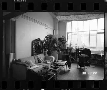
I love the date imprints on photographs and I want to attach an external date back on an analogue camera that doesn't have a date back (yet).
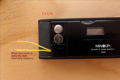
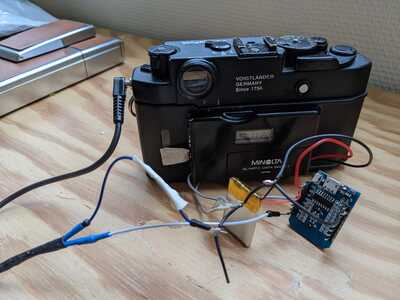
I've already extracted a date module from another camera and l’m able to manually trigger the date imprint process (by making the 2 yellow cables touch), but I'm having trouble to exploit the camera signal to imprint the date when a photo is taken.
My date module looks like this :
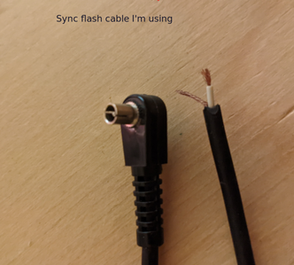
On the other end the sync cord I use from the camera looks like this :
I tried connecting these 2 parts and was able to imprint the date for shutter speed slower than 1/125s
It seems that the signal (closing a circuit) sent by the camera is too fast to be caught by the date module.
I've already posted on another forum and have been suggested to use a 555 timer, but I ended up building quite a "big" circuit plus electricity was leaking inside the camera body (the date imprinting could be triggered simply by touching the camera body)
So, I wanted to know if you had any other suggestions in order to use the camera signal ? (bonus if we can keep things simple and compact)
Thanks for reading 🙂
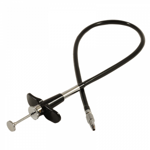
@nicolas Does the camera have any kind of remote release? If it does, change your operation to use that as your shutter release and tie the date imprint signal into that. That is just a simple switch with no issues re timing etc involved in the Synch outlet.
First computer 1959. Retired from my own computer company 2004.
Hardware - Expert in 1401, and 360, fairly knowledge in PC plus numerous MPU's and MCU's
Major Languages - Machine language, 360 Macro Assembler, Intel Assembler, PL/I and PL1, Pascal, Basic, C plus numerous job control and scripting languages.
Sure you can learn to be a programmer, it will take the same amount of time for me to learn to be a Doctor.
Hello @zander, thanks for taking the time 🙂
Unfortunately It's an old camera, a Bessa R3a, I can screw a soft release cable on it, but it's mechanical, not electronical 🙁
@nicolas There are still a couple ways though. The first is to use that mechanical release but add a micro switch under the handle to trigger the date. Another approach is to use a sound activated switch you can make with an arduino or esp32 or esp8266.
First computer 1959. Retired from my own computer company 2004.
Hardware - Expert in 1401, and 360, fairly knowledge in PC plus numerous MPU's and MCU's
Major Languages - Machine language, 360 Macro Assembler, Intel Assembler, PL/I and PL1, Pascal, Basic, C plus numerous job control and scripting languages.
Sure you can learn to be a programmer, it will take the same amount of time for me to learn to be a Doctor.
switch you can make with an arduino or esp32 or esp8266
I've already been able to make it work with an esp8266 with a code like this :
int inputPin = D3;  // Sync flash connected to camera
int outputPin = D4;  // Date back module

void setup() {
  pinMode(outputPin, OUTPUT);
  pinMode(inputPin, INPUT_PULLUP);
}

void loop() {
  if(digitalRead(inputPin) == LOW) { // Low is when the circuit is closed (aka when a photo is taken)
    digitalWrite(outputPin, HIGH);
    delay(100);
    digitalWrite(outputPin, LOW);
  } else{
    digitalWrite(outputPin, LOW);
  }
}
But I'll have to power the board so I'll need batteries, and maybe a switch on/off too ? I have now idea how much the board will consume, but I'm afraid it'll make my project too big and cumbersome...
So I looked into PIC microcontroller, they are smaller and I guess they demand less energy ? but I've never used one, do you think it could be a good idea ?
to use that mechanical release but add a micro switch under the handle to trigger the date
Yes, the mechanical solution is definitely my plan B , do you have a "micro switch" in mind ?
Thanks 😀
@nicolas Remember esp8266 come as small as a large postage stamp and if you use deep_sleep after each shutter press it will only need one or two coin batteries. Sorry I don't know anything about PIC. No micro switch in mind, all you need is anything to complete a circuit from ground to switch to pin. even 2 small pieces of brass shim stock cut to size would work.
First computer 1959. Retired from my own computer company 2004.
Hardware - Expert in 1401, and 360, fairly knowledge in PC plus numerous MPU's and MCU's
Major Languages - Machine language, 360 Macro Assembler, Intel Assembler, PL/I and PL1, Pascal, Basic, C plus numerous job control and scripting languages.
Sure you can learn to be a programmer, it will take the same amount of time for me to learn to be a Doctor.
Just extend your yellow wires and run them up the length of the cable and hot glue the bare ends of them onto the thumb rest and the limit plate at the bottom. Hot glue is a non-conducting medium so that should insulate them from being triggered by the metal rod and plate. All you need to do is make sure that the bare wires touch each other when your thumb presses down the plunger button.
That way you can still trigger the date burner with the same method of connecting the two yellow wires.
Anything seems possible when you don't know what you're talking about.
@zander Hello !
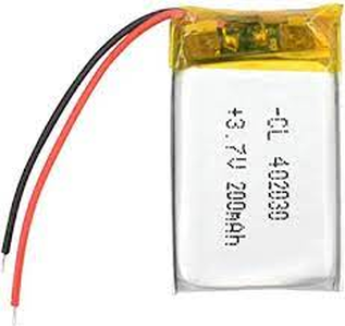
You are right, I realized esp8266 are pretty small and battery can be pretty small too :
Plus I guess I can power both the date module and the esp8266 with the same battery 🙂
I've also been able to simplify my code and to enable deep sleep, so it starts to look like a good solution 😀
My code for anyone finding this post in the future :
int outputPin = D6; // Date back module

void setup() {
  pinMode(outputPin, OUTPUT);
  digitalWrite(outputPin, HIGH);
  delay(100);
  digitalWrite(outputPin, LOW);
  ESP.deepSleep(0, RF_DISABLED);
}

void loop() {

}
@Will Thanks for your suggestion I keep that in mind 🙂
@nicolas Good work. Have you seen how small an ESP-01 is?
First computer 1959. Retired from my own computer company 2004.
Hardware - Expert in 1401, and 360, fairly knowledge in PC plus numerous MPU's and MCU's
Major Languages - Machine language, 360 Macro Assembler, Intel Assembler, PL/I and PL1, Pascal, Basic, C plus numerous job control and scripting languages.
Sure you can learn to be a programmer, it will take the same amount of time for me to learn to be a Doctor.

