Hi,
I'm new to circuit design and I'm trying to figure out an easy way to automatically switch circuits on and off. Ideally, I would like for the switch to happen when a certain voltage is reached across a battery that is recharging. When the threshold voltage is reached I want to turn off a circuit and turn on another circuit.
There are actually three circuits involved so when circuit 1 is switched on, circuit 2 and 3 should be switched off.
The ON and Off of the circuits will rotate like this:
circuit # 1 on switches 2 and 3 off
circuit # 2 on switches 1 and 3 off,
circuit # 3 on switches 1 and 2 off
then REPEAT (back to circuit # 1 on switches 2 and 3 off, etc., etc.)
FYI, Each circuit will be running off its own 12V battery
I was trying to avoid using an Arduino as that seems like it may take a while to learn. I thought Mosfets as switches might work but not sure how to configure them.
Hope this makes sense. Any help would be greatly appreciated.
Thanks for your time.
Scot
Hi:
Comparators are what you want! They are essentially OPAMPs with no feedback resistor. Essentially they have two inputs, a reference and the other is the voltage you wish to monitor. When the monitored voltage pin exceeds the reference pin, it will switch its output, so NO microcontroller is necessary at all. I don’t have any specific examples but they are everywhere in many form factors.
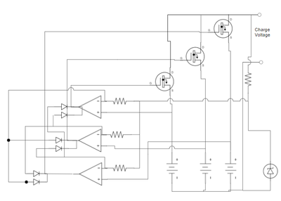
First let me say that what you are wanting to do most likely will be easier to do with something like an arduino. I am attaching a conceptual drawing that with some more work "might" achieve what you want. Its goal is to use the three comparators to match the battery to be charged to a zener diaode to determine if the battery needs to be charged. If it does the output of the comparator output goes low. This low signal does two things... It pulls the other two battery's comparator reference lines low so they will stay off while the one battery is charging. and it also puts low voltage on the n channel MOSFET to apply current to the charging battery. Once the battery is charged the comparator's output will go high, turning off the charging current from the MOSFET and it releases the sense inputs of the other two batteries. If either of the other two batteries need to be charged, the one with the fastest circuitry will cause its comparator to go low and its battery will start charging.
There are a number of foreseeable problems with this circuit that will require additional work, one of which, there is no hysteresis in the comparator circuits. Also if there is only two batteries being charged the circuit may become unstable. I'm sure there are more problems but it was fun puzzle to try to solve without using a lot of components. P.S. A manual rotary switch to switch between the batteries would probably be more practical. Please for give the drawing layout. It is free software and you can tell it
.
it was fun puzzle to try to solve without using a lot of components.
I'll have to study your diagram a bit more to understand it, but I've learnt a new word already (hysteresis) 😀
And seeing you might like to solve puzzles I wonder if you would like to suggest a circuit, a rather distant cousin to the circuit you show to be sure, that achieves the following. A circuit that, when connected to a battery, can have a cut-off voltage dialled in (maybe by looking at a voltmeter and tweaking with a potentiometer to indicate the cut-off voltage specified). When the cut-off voltage is reached it has an output pin (or pins of 5volt and 3.3volts) so that a signal can be sent to an arduino or Rpi indicating that action pending a current cut-off has been reached. It would then monitor on another pin to see if the Ardunino or RPi signals its time to cut the current from the battery off having taken some action such as 'robot go to a parking place', and in the case of the Rpi, having shut itself down. The circuit would then flip a relay (or something) to disconnect all power feeds from the battery. My thoughts are that one could connect different types of batteries and set the cut-off voltage appropriate to its type.
This is probably a rather complicated thing to achieve, and its beyond my capabilities 🤔 but maybe you could think of suitable solution. 😎
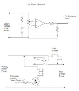
First some disclaimers: No component values are shown since the actual power voltages were not given, so again this is a conceptual design. Second I haven't tested the design so use at your own risk and if you do use some of this design please test before applying to your main project. Finally please forgive the stupid arrows this drawing software wants to add to the drawing (free online software).
Ok, if I understood your needs properly the drawing shows two separate circuits to accomplish them. The top circuit monitors the battery voltage and compares it to a reference. Lets say you have a 12 volt battery to be monitored and low voltage is define as 10 volts then the zener diode would need to be something less than 10 volts and when 10 volts was applied to the battery input the pot would be adjusted to cause the comparator to go low at that threshold. The output of the comparator would send a high signal to the processor while the battery is above the threshold and low when the battery is below it. Note: a simpler approach could be to use a voltage divider to bring battery voltage down to the range of the A to D converter in the Arduino and use software to decide when the battery is low.
The second circuit uses an n channel MOSFET (a NPN transistor could be used) to activate a relay to keep power on. The MOSFET would be driven by the processor output. As long as the processor keeps a high signal on the MOSFET the power stays on. Once a low signal is received the relay is disengaged and the power is turned off. To get the system started, the start button is depressed and held until the processor boots up and brings the output high the activates the relay. Note: I noticed I forgot the fly-back diode on the relay... I warned you about these designs 😉
Thanks for giving this challenge a go. I was thinking along the lines of the battery voltage of a range of 14 - 7.4 volts for fully charged lead acid, lipo or nimh batteries etc and to set an appropriate minimum voltage cut-off depending on the battery type and its capacity that is selected for the power source. A one circuit design for all. 😀
Your design is my starting point to experiment, and not to worry about me doing something too silly with your design, much experiment will take place on the bench before anything is put into a robot. The worst I have done thus far in my electronic tinkering is to short out a pin on an Rpi a while back and destroyed it). I will be chewing away at this project starting with trying to put your design into iCircuit (which is a free and simple circuit emulator that runs on my iMac). I'm taking it that the curly wire around the pole the relay coil. I'm thinking of using IN4007 for the flyback diode. Also I have some op-amps which I know can be used as comparators, but I know there are also comparator chips so I think I should order a few for my parts collection. If you have a suggestion as to what comparators would be good comparator chip to use then please do let me know.
Thanks again for coming up with a circuit idea so quickly, much appreciated.
I'm taking it that the curly wire around the pole the relay coil. I'm thinking of using IN4007 for the flyback diode.
Yes the pole with the curly wire is the relay coil. The flyback diode can be most any diode you have around because the relay coil will be relative small. As far as package components like a comparator I won't be much help for recommendations. I've been out of electronic design for many years (like 40). Not only has much changed but I've forgotten most of what I knew. Just make sure the supply voltage for the comparator can withstand the voltages you will be using. Using an OpAmp is fine but most are designed to work on + and - voltage. So if you use it with a single supply (like +12 volts) they can perform a little eradicate if both inputs are close to ground. There are also challenges with the output voltage if powering the OpAmp with say 12 volts and feeding a logic circuit that's expecting only a 3.3 V input.
Best of luck with your project! It sounds very interesting.
The ON and Off of the circuits will rotate like this:
circuit # 1 on switches 2 and 3 off
circuit # 2 on switches 1 and 3 off,
circuit # 3 on switches 1 and 2 off
then REPEAT (back to circuit # 1 on switches 2 and 3 off, etc., etc.)
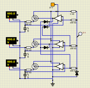
I was learning how to use a circuit simulation software and decided to try it out on the circuit I initially proposed to you. There are only a couple of changes even though the circuit looks somewhat different. The diode arrangement is the biggest change as the original design cycled through each of the circuits creating an oscillating effect. If you watch the video of the simulation you will see the top MOSFET turn on until the battery ( Note: For the simulation I used a 100K resistor and a 100mf capacitor to simulate the charging of batteries) is charged to 12 volts. Once the top battery is charged then it moves to the second battery and then finally the third.
Link to simulation video>>> https://photos.app.goo.gl/cBqhkKhxukgn4k2W6
I didn't even know those existed!
It seems like a good option. I will look into learning about comparators.
Thank you!
Scot
This is a great start. You have introduced me to comparators and the Zener diode. This is a big help!
Thank you!
Awesome! I watched the video and I am excited to study it until I fully understand it. I'm curious if you would share the name of this circuit simulation software? It seems like an amazing tool.
This is an interesting puzzle to solve. Thanks for sharing your creativity and time!
Thanks again.
Scot V.
Yeah, not problem. I just found the simulation software, SimulIDE, yesterday and it is awesome. I first used the 3.10 version and had a lot of trouble with it crashing. But after some reading I found out that the version 3.10 had some bugs and the latest version (3.12-SR8) was much better. The best feature that I just started using today lets you include an Arduino Uno in you circuit and then write code for the Arduino. The site has tutorials that are helpful as the simulation UI is somewhat plain and not intuitive when you start. But once you get the jest of it its easy to use. Here's the download link>>> https://simulide.blogspot.com/p/downloads.html
I just found the simulation software, SimulIDE, yesterday and it is awesome.
I concur. Thank you for this interesting link !
Eric
Yes, I don't even have my Arduino Uno yet but I've been able to write code and build circuitry for a project I'm I want to do and test it out on the simulator. It is a great time and money saver.


