Hi @inq and @fastrunner08,
Temperature - @davee is unconditionally one of the hardware guys. But, the ESP8266 I specified above is rated -55ºC to +125ºC. I've made several projects that I've 3D Printed ABS Housings for. I even totally sealed them (melted ABS plastic)
When I mentioned 70 Celsius, this was simply a common figure that has been in common usage over at least 5 decades, maybe longer, and that I think still frequently appears. Remember, a circuit usually consists of a bundle of different devices, all with their own specifications. Of course, the 'proper' approach is to carefully study every parameter of the data sheet for everything from the microcontroller to the washers under the screws that hold the box together, but if you can keep the temperature below about 70 Celsius, including allowance for self-heating, then it stands a reasonable chance of working without spending too many years on the thermal aspects. Yes, you can go higher, but remember you must ensure it applies to every component, and the higher the temperature, the more likely parts will have a short lifetime.
---------
@inq is the ABS expert, but Google's first attempt said:
While ABS possesses a good thermal range, its heat resistance is fairly limited. It's typically used in environments where temperatures range from -20 °C to 80 °C (-4 °F to 176 °F).
So, if that is approximately true, again 70 Celsius seems a reasonable rule of thumb for 3D printed parts that are going to be part of the solution.. and considerably lower for PLA.
------------
Whilst a commercial unit would combine the mains electric wiring with relays, etc with the microcontrollers, personally I would be tempted to separate them, since development work usually requires a lot of 'hands-on' fiddling, when the chance of a stray finger or meter probe touching mains potential is considerable. Hence, I would aim for:
- one box with mains switches (including a 'cut all power' emergency override), relays (solid state or electromechanical), maybe mains to low voltage power supplies, etc.,fuses and other mains safety trips,
- a second box with microcontroller, wiring to sensors, outputs to drive the relays in the other box, possibly accepting low voltage power from first box
Consider, Does it make sense to put the boxes in different locations? There is no universal answer to this question, it depends on the circumstances.
Obviously, this is only a broad outline suggestion. Consider it, but do not regard it as a requirement or an instruction. The responsibility of what you implement is totally yours.
Best wishes, and good luck, Dave
@davee @fastrunner08 @inq Just mount the box outside on the shady side of the silo. Max temp there is 40C.
First computer 1959. Retired from my own computer company 2004.
Hardware - Expert in 1401, and 360, fairly knowledge in PC plus numerous MPU's and MCU's
Major Languages - Machine language, 360 Macro Assembler, Intel Assembler, PL/I and PL1, Pascal, Basic, C plus numerous job control and scripting languages.
Sure you can learn to be a programmer, it will take the same amount of time for me to learn to be a Doctor.
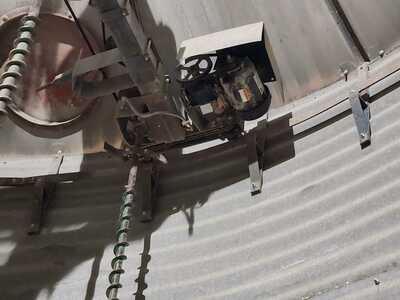
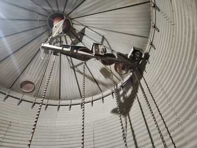
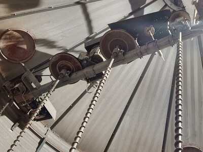
Sorry for the delay, have been out harvesting crops in between working my full time job. I finally got into the grain bin tonight to take some photos as promised. You will see the large motor in the middle, that is what spins the augers via the pullies. The close of up of the smaller motor is the one on the track that rotates the system around the bin. Small motor is 110v big one is 220v.
I'm thinking i want to mount the sensors on the outside most auger and inside most auger. The motor has a double pulley one belt goes to the left auger and right auger of the motor. those two augers also have double pulleys that then send a belt to the outside most and inside most auger. So in theory if one of the inside belts breaks it would stop the two augers which is why i think i can get away with sensors only on the outside and inside most ones.
I would have to mount the box on the frame there, or purchase a different rotary. Any system that isn't on that beam would had to have a rotary as the system spins. It has a rotary right now, but only for 3 wires. the two hot legs for the 220, and the neutral for the 110v.
@fastrunner08 I think the consensus is to measure the current draw on the motor. I would also add a simple special limit switch (it's special because it has a small wheel on the end of the arm) against the belts. This way if a belt breaks you get a signal, and if the motors get overloaded you get a signal.
Yes, the fact the belts are rotating around the silo may require a device that someone posted here a few days/weeks ago. Hopefully someone will remind us what it is. The motor loads can be attached at the point there is no rotation.
Another solution to the rotating belt sensor is to use a battery operated setup. I think (subject to testing) is to put the MCU to sleep and use a pin wakeup caused by the belt breaking. That way a relatively small battery will last for months or longer. Just pick the best MCU in terms of sleep current, the code is probably a dozen lines or so.
First computer 1959. Retired from my own computer company 2004.
Hardware - Expert in 1401, and 360, fairly knowledge in PC plus numerous MPU's and MCU's
Major Languages - Machine language, 360 Macro Assembler, Intel Assembler, PL/I and PL1, Pascal, Basic, C plus numerous job control and scripting languages.
Sure you can learn to be a programmer, it will take the same amount of time for me to learn to be a Doctor.


