Hi all, I think there's some confusion about what I've tried and when so I hope this clears up some of that.
The OP can easily prove it by simply removing the I2C wires from the Pi, connecting the board VCC to the Pi 5VDC and the board G to the Pi G as some have done and then measuring what voltage is on the board's I2C pins.
This occurred to me but apparently it is hard to get a good reading for the voltage of an i2c connection because its state fluctuates? I was getting nonsensical numbers when I tried it before, though I admit I'm not an expert with a multimeter. I had made the setup as you described then ran the probes, one test over two different points on the i2c line and another test with the + probe on i2c and the other on the pn532 board's ground. I will look into this more tomorrow.
Just a picture of my multimeter, I'm not probing anything.
As always I appreciate the help. Eventually I would like to be able to design small circuits so regardless of the answer I appreciate the discussion of the components' interactions not ending at "it works".
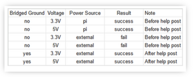
@davee The OP has at least attempted the test I suggested. Although using a VOM is not ideal, he did have the guts to believe the other evidence and at least try connecting 5V both from the Pi power pin and from an external supply. It WORKED. Here are his results.
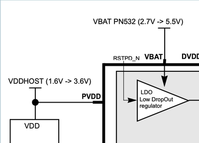
NOW, as a general rule, of course Dave is correct, you should not mix voltages unless there is some sort of isolation and if given a choice, use the common voltage. In this case it works at both voltages but since we know from page 85 that below 3.4V the LDO VR is just 'passing thru' the nominal 3.3V it makes sense to either use a guaranteed PSU or use a voltage > lowest usabel but < highest usable. I have done this type of arrangement when I lived in my RV. I had a huge 12VDC supply, so I used a buck converter to get it down to 7ish V then a linear VR to take it to 5V. If I also or instead needed 3.3V the regulated 5V would become the input to the 3.3V linear VR.
The 2nd pic is the page 85 info.
The 3rd pic shows in block diagram style (and Dave will point out that this is the 'chip' diagram, not the 'board' diagram). I choose to believe that the board designers are smart enough to follow the same philosophy but I, like Dave have no proof one way or the other, other than the OP tests that at least appear to support the claim that indeed VCC can be 5VDC. What I see that I find interesting is the voltage range for VBAT (2.7 - 5.5) and the voltage range for VDDHOST (1.6 - 3.6)
The datasheet has a lot of info and refs to power, and I see a few that say there are 2 basic power levels that it refers to as HOST and Battery.
The testing that the OP has done confirms my findings, but I have enough respect for Dave to also be cautious. IF a reliable 3.3V external supply can be used, use that, as a second choice, an adjustable external supply of roughly 3.6 to 3.8 would be good (just make sure it stays above 3.4) and the third choice is 5V.
Much thanks to @allocsb for testing the device and risking his Pi. I was going to order the board this morning to do the same test but now I don't need to.
First computer 1959. Retired from my own computer company 2004.
Hardware - Expert in 1401, and 360, fairly knowledge in PC plus numerous MPU's and MCU's
Major Languages - Machine language, 360 Macro Assembler, Intel Assembler, PL/I and PL1, Pascal, Basic, C plus numerous job control and scripting languages.
Sure you can learn to be a programmer, it will take the same amount of time for me to learn to be a Doctor.
@allocsb If yoiu have a scope, you may be able to see what is happening better, some scopes even have I2C decoding. Or maybe a digital logic probe, but I don;t know if they show voltage level.
First computer 1959. Retired from my own computer company 2004.
Hardware - Expert in 1401, and 360, fairly knowledge in PC plus numerous MPU's and MCU's
Major Languages - Machine language, 360 Macro Assembler, Intel Assembler, PL/I and PL1, Pascal, Basic, C plus numerous job control and scripting languages.
Sure you can learn to be a programmer, it will take the same amount of time for me to learn to be a Doctor.
Thanks to both of you, for your interest, contributions and patience.
From the table above, my understanding is that the penultimate line is saying that it works when you supply 3.3V, from a 'separate' supply to the PN532 board, with the grounds of the R-Pi and PN532 supplies linked.
This is good news, because it implies:
- that the I2C communications are 'getting through' the superfluous 'logic level voltage converter', in spite of it only being powered to convert 3.3V logic to 3.3V logic, rather than 3.3V to 5V, which was the intention of the PCB designer.
- Because the power going to the PN532 board is only 3.3V, and there are no 'boost/step-up' power supplies, etc., then the highest voltage it can send back to R-Pi via the I2C pins is 3.3V, making it compatible with the R-Pi.
Notes:
-
- A multimeter can verify the voltage going to the PN532 board is 3.3V.
- Measuring the maximum voltage on an I2C bus with a multimeter should be possible IF you can ensure there are no messages being sent from both the R-Pi and the PN532, because messages mean that the bus will be near 0V for some of the time, which will confuse a multimeter, but they should not increase the voltage above the value when the bus is 'quiet'.
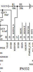
- I would only expect the R-Pi to send messages when it is running a programme that 'talks' to the PN532. The PN532 might 'automatically' send messages when powered - I haven't looked for details on its internal operations. One trick might be to force the PN532 into reset. The reset input is pin 38, which according to the board circuit diagram is connected to the junction of two resistors, R1 & R9:
Connecting the junction of those two resistors to ground would force the chip to reset. If you try it, make sure you do not accidentally connect the other side of R1 to ground, as it is the incoming 3.3V power line!
- I would only expect the R-Pi to send messages when it is running a programme that 'talks' to the PN532. The PN532 might 'automatically' send messages when powered - I haven't looked for details on its internal operations. One trick might be to force the PN532 into reset. The reset input is pin 38, which according to the board circuit diagram is connected to the junction of two resistors, R1 & R9:
- This is one of those times an oscilloscope is handy, as you can look at the I2C bus, even when it is sending messages. Of course, acquiring a 'scope probably means more expenditure.
-------------------------------
Referring to various assertions that have been written in this thread:
- The R-Pi microcontroller GPIO pins are designed for the voltage to be strictly in the range 0V to 3.3V at ALL times. Applying a voltage for less than a microsecond that is more than about 0.25V outside of this range, RISKS permanent damage.
- A risk is not a certainty, it is a possibility. It is like smoking and lung cancer. Just because someone smoked for 70 years, and didn't suffer from lung cancer, doesn't mean it is safe for everyone else to smoke.
- I doubt if all software engineers are aware of the internal silicon design of a GPIO pin, including the ESD protection measures. In reality, I expect there are a lot of hardware engineers who are not conversant, although hopefully most will have learnt that exceeding the maximum voltage ratings on a pin is a really bad idea.
- Oversimplifying, each pin has two diodes, usually connecting to the incoming power rails (say 0V and 3.3V), so if the voltage on the pin exceeds about -0.3V in a negative direction, or about 3.6V in a positive direction, one of the diodes will conduct in an attempt to draw enough current to prevent the pin voltage going any further out of the allowed range. The diodes are physically small, and only designed to discharge a small amount of static electricity, so if they are connected to a supply with a 'substantial' power capability, the current may become so high, it will physically damage the silicon and metallisation in that area of the chip. In some cases, the result may be an instantaneous failure, complete with holes in the package and magic smoke, but in many cases it is more subtle. Indeed, it might only show up when a unit goes into mass production, and the factory gets 10 times as many warranty returns as it expects.
- So I do not mean to be disrespectful, but I would treat statements like 'the library developer said the Pi can power the board from either the 3.3 or 5' with extreme caution ... not that I think they are deliberately trying to mislead anyone, but rather, I doubt if they have sufficient information, to make a reliable judgement.
- To be meaningful, such a judgement would include measuring the current flows, and assessing the ability of the protection circuits to handle that current. I have never seen a data sheet that provides any details of the protection circuits, so this means examining the physical silicon, metallisation etc, which is also not published, in order to be able to figure out the consequences. Or possibly achieving the same result by testing on physical devices and then examining the device with electron microscopes, etc.
- Hence, I would interpret the above description as "I have reports that one or more people have done it, and got away with it." Does that mean it hasn't degraded their device, or that the device hasn't failed since? There is no way of knowing.
------------------------
Sorry, I know that sounds rather 'doom and gloom', but I am trying to be honest. We can all learn lessons from the occasional 'puff of magic smoke', and hope it came from something cheap and easy to replace, but I think we should also try to understand and apply the fundamentals, and reduce the number of 'puffs' we create.
----------------------
In terms of 'What next?', then it seems you have a scheme that provides enough power for the enumeration test, but full operation of the whole project may be more demanding. In particular, I note the PN532 current demand is listed as 150mA with a VBat of 3.4V, so I would aim for a supply that can comfortably supply at least twice that figure (300mA), to minimise the chance of it being a problem. (Commercial designers would probably aim much closer to 150mA, but they will produce multiple prototypes, etc. and then skimp it to a minimum to reduce production costs.)
Clearly, 150 mA is rather high to expect the R-Pi to be able to supply it, although, depending upon its own power consumption, which is software dependent, it might be able to. A separate supply is certainly a wise precaution.
The R-Pi itself can also demand a substantial current. Please ensure its supply is at least as capable as the recommended R-Pi 4 'official' supply unit.
--------------------
When connecting two units, like the R-Pi and the PN532, via a network like I2C (or SPI or 'UART'), with each unit having an independent supply, be aware that 'strange' behaviour may be observed, if the power is applied to one unit before the other. In brief, the powered unit may send enough power across the network connections to the unpowered unit, to put the unpowered unit into a 'weird' state, from which it cannot escape when its power is applied. Removing power from both units, and then re-applying it in the reverse order, will usually 'fix' the problem.
Curiously, this is also partially down to the ESD diodes I mentioned above. With luck, you will never see the problem, but if you do a number of projects, it will probably arise sooner or later. For now just be aware of it, because it tends to be intermittent, and can be really confusing when you are developing software, etc. and occasionally the whole system just hangs up.
--------------------
Best wishes, Dave
Hi Ron @zander,
@davee The OP has at least attempted the test I suggested. Although using a VOM is not ideal, he did have the guts to believe the other evidence ...
Sorry, but in this case, I believe you should consider the consequences of your actions.
There is no 'other evidence' ... nor are there 'alternative facts', to use a fashionable euphemism.
Supplying significantly more than 3.3V to the PN532 board, whilst it was connected to an R-Pi GPIO, was simply reckless, not courageous.
It wasn't even a step that provided anything beyond that of the same wiring configuration, but with only 3.3V supplied to the PN532.
I sincerely hope it hasn't damaged the R-Pi, but as I have tried to explain, that is not feasible to determine with any certainty.
--------
The facts are simple:
The PN532 chip 'alone', using the I2C interface', without the PCB addition of a 'logic voltage level converter', would be fine for the R-Pi ...
but 'traditional' 5V Arduinos would then need a voltage level converter.
This board will directly output the incoming board power voltage on the two I2C pins. Hence, if this voltage exceeds 3.3V, it has the potential to damage R-Pi GPIO pins connected to it.
------------------
The observation that 3.3V logic inputs sometimes appear to 'survive' being driven by a higher voltage than 3.3V, when the voltage source has a medium to high value impedance, is unsurprising. The ESD diodes that are part of the GPIO pin structure will attempt to 'dump' the excess energy into the power lines, as if it were an ESD spike. However, they are not designed for this purpose, and may well be damaged.
Although, the source of the excess voltage (the 'logic voltage level converter' is likely to be much more robust than the GPIO pin diodes, in other circuits, the increased current flow might also damage the source.
Unfortunately, unless you slice into the R-Pi processor and take some (electron) microscope pictures, you will only find out if it was damaged by the experience, when it fails prematurely.
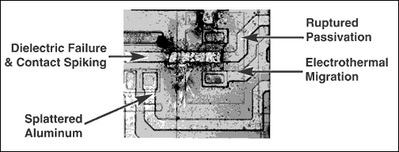
It is easy to find pictures of such damage caused by electrostatic discharge, e.g. from
https://www.analog.com/en/resources/technical-articles/esd-protection-for-io-ports.html
It is probably harder to find ones caused by connecting a pin to a voltage beyond its rating, because there is no sensible reason for anyone doing it, whilst electrostatic charges are much harder to eliminate.
-------------------------
The LDO diagram and associated text in your same message are irrelevant. The PN532 on its own would have 'contained' the voltage up to 5.5V to the voltage regulator input.
The problem is caused by the PCB designer adding a 'logic voltage level converter', which also connected to the incoming (up to) 5.5V supply ... something the chip designer and chip manual writer would never have envisaged.
Similarly, your past experience with voltage regulators etc. is not directly relevant to this unusual situation, because you would never have reduced a voltage with a regulator, from say 7V to 5V, and then reintroduced the 7V to the same circuit that was being powered by the 5V output.
------------
Sorry, Ron, but you are wasting a lot of all of our time on this one. I'll leave you with a thought to ponder.
There is a lot of crossover and similarity between computer hardware and computer software, but they also differ.
In particular, a piece of software (alone) never suffers failures. It is either always flawed or always correct. Of course, bugs may become apparent, that had previously not been noticed. Changing circumstances around a piece of code may reveal a new problem. The requirements of a piece of code may change, and it may need changing to meet the new situation. Also, a program in a machine may become corrupted, by a memory bit changing from 1 to 0; but that is a hardware failure.
Software, itself, cannot 'fail' in the way that a chip can die.
This statement may not sound very profound or novel, but it has implications. In particular, a software program is 'infinitely' robust, in that, for the same inputs, it will always perform the same 'task' to give the same result. (True random number generators rely on hardware 'uncertainities'!)
However, hardware can be 'mutated' by its experiences. Two enmeshed gears will impose wear on each other, and eventually deteriorate to the point that they no longer rotate in harmony. Electronic parts also degenerate and eventually fail. If the gears are asked to transmit too much power, or the electrical parts are exposed to excessive voltage or current, they will wear more quickly. Depending on the extent of the overload, the effects might be immediately apparent or may not show up for years.
By contrast, you cannot 'overload' software. You can 'break' its intended functionality, and the effect will be immediately apparent, say by trying to calculate 16 X 17 and put the result in an 8-bit integer, but the basic code is not 'broken' by the experience. It will still be able to calculate and store 5 X 3, assuming it could do it previously.
---------
So while, 'testing to destruction' is done to both hardware and software in certain circumstances, when it is applied to hardware, it is acknowledged that the result is really only fit for scrap or salvage, even if it may have appeared to survive, and a replacement is likely to have a cost. Meanwhile, the software code is guaranteed to be just as good as new!
---------
Best wishes and take care, Dave
@davee @allocsb I just bought 6 of them so I can see for myself, but according to Bill, 5V I2C is actually ON or positive at slightly less than 3V so that explains what I think I see where the 5V input is converted to 3.3V BUT I will test that observation. I will let you know.
First computer 1959. Retired from my own computer company 2004.
Hardware - Expert in 1401, and 360, fairly knowledge in PC plus numerous MPU's and MCU's
Major Languages - Machine language, 360 Macro Assembler, Intel Assembler, PL/I and PL1, Pascal, Basic, C plus numerous job control and scripting languages.
Sure you can learn to be a programmer, it will take the same amount of time for me to learn to be a Doctor.
Hi Ron @zander,
Good luck with your investigation. Remember with buses, and indeed any digital signals, there is not just 'one' decision voltage, but rather there are typically three voltage ranges. e.g. the old 7400 style TTL was something like:
- 0 to 0.8V .. a zero/low
- 0.8V to 2.4V ... the circuit hasn't decided! Sometimes shown as X or unknown.
- 2.4V to 5V .. a one/high
Note, I just plucked those voltages from thin air ... so they are not necessarily accurate, but hopefully show the kind of figures to look for.
If you find a net in a circuit, or in a network like I2C, that is staying in the middle range, it often, but not always, means something is broken.
The I2C voltages will be different, so please read the relevant documentation to find them. Plus, of course, I2C for 5V will be different for I2C for 3.3V, so you need to look up both ranges.
--------
Best wishes and happy researching! Dave
@davee I will be using my scope that has built-in I2C decoding. I will report back.
First computer 1959. Retired from my own computer company 2004.
Hardware - Expert in 1401, and 360, fairly knowledge in PC plus numerous MPU's and MCU's
Major Languages - Machine language, 360 Macro Assembler, Intel Assembler, PL/I and PL1, Pascal, Basic, C plus numerous job control and scripting languages.
Sure you can learn to be a programmer, it will take the same amount of time for me to learn to be a Doctor.


