Hello,
I am starting to study electronics and I have hard time in understanding the astable multivibrator (the one made with 2 BJTs and capacitors).
I understand that general principle: it's based on the RC constant of each capacitor and charging/discharging times but what I don't get is the circuit itself:
I know that polarized capacitors have to be mounted with the anode to the point with upper potential and the cathode with lower potential.
Antil now, I saw using capacitors like decoupling capacitors getting the charges on the + plate and, after release them from the same plate in the opposite direction.
And the cathode was always connected to the ground.
(Only fading in or fading out LEDs)
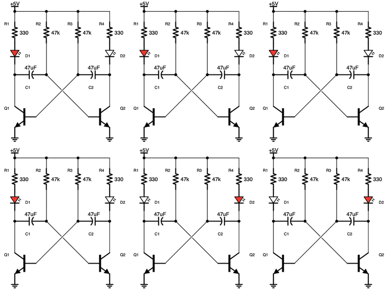
So, in the picture, why am I connecting the cathode to the 5V trough the 47K Ohm resistance?
Please, if you have some URL where I can understand this type of connection, send me, please?
I am really stuck!
Thanks
So, in the picture, why am I connecting the cathode to the 5V trough the 47K Ohm resistance?
You are not connecting the cathode to the 5v via the 47K resistor.
The 47 uF capacitor does not pass direct current. It does however pass a changing value of a current.
You have two single transistor amplifiers in the common emitter configuration where the output of one goes to the input of the other via the 47uF capacitor and vice versa. This results is an oscillation between the two transistors where one goes high and the other low and then vice versa. The oscillation rate depends on the RC constant that determines how fast the capacitor charges and discharges.
These two I found that might make it easier to visualize.
https://www.build-electronic-circuits.com/astable-multivibrator/
Hi @boggiano,
Your specific question is
why am I connecting the cathode to the 5V trough the 47K Ohm resistance?
@robotbuilder has provided a good comprehensive link about astable circuits, but in case you are still a bit confused with respect to your question, maybe this simplistic approach will help:
NB I use the terms 'positive' and 'negative' terminal rather than 'anode' and 'cathode' for the simple (biased) reason that that reflects my experience in conversation over several decades. Similarly, I prefer to see a '+' on the capacitor symbol to indicate the 'positive' connection, as it matches most component markings. (Others may have the opposite experience and views.)
- For most purposes, consider electrolytic capacitors to be the same as any other capacitor when looking at the circuit. That is replacing the two 47uF electrolytic capacitors with 'non-polarised' capacitors (e.g. ceramics) should not affect its operation as a multivibrator. Choosing electrolytics is generally based on 'convenience' ... for capacitances of more than about 1uF, an electrolytic capacitor is likely to be smaller and cheaper than its non-polarised cousin.
- An electrolytic capacitor has an internal structure which involves 'growing' a very thin insulating layer on one of the capacitive plates at the manufacturing phase, typically by passing an electric current through the component to 'form' the capacitor. In subsequent usage, the capacitor must be connected such the 'positive' terminal is kept at a positive potential with respect to the 'negative' terminal. Applying a reversed potential difference, even for a short time, can destroy the insulating layer and hence the component as whole.
- https://www.tdk-electronics.tdk.com/download/530704/6ad5ed9e1ff4f727c328cb92da2adf2b/pdf-generaltechnicalinformation.pdf gives more infomation from one manufacturer
- So, when you come to a circuit like the multivibrator, it is necessary to determine the potential differences the capacitor will encounter ... to make sure you are not going to destroy the capacitor(s)
- The negative terminal of each capacitor is connected the base of a transistor, and the emitter of that transistor is connected to 0V line. So assuming the transistor is 'general purpose' silicon bipolar junction type, the base voltage will not exceed about 0.7V in normal operation, 0.6V (max) being typical.
- The positive terminal of each capacitor is connected to the collector of the 'mirror image' transistor. If the transistor is 'switched off', the collector current will be extremely small, and the collector voltage will rise towards, but not reach, 5V .. say maybe 3V.
- If the transistor is 'switched on', the current will flow through the 330 Ohm resistor and LED, causing a voltage drop across the resistor and LED, to the point where the collector voltage is close to that of the base voltage of the same transistor ... say 0.6V (or slightly higher)
Thus, each capacitor will experience two alternate conditions:
- Both terminals of the capacitor at roughly 0.6V with respect to 0V line. Potential across capacitor approximately 0V.
- 'Positive' capacitor terminal at 3V with respect to 0V (say), 'Negative' terminal at 0.6V with respect to 0V. Potential at 'positive' capacitor terminal with respect to 'negative' terminal of 2.4V
Hence, the circuit should be suitable for electrolytic capacitors, providing the 'negative' capacitor terminal is connected to the base of the respective transistor.
---------
Hope this helps -- it includes a few simplifications and assumptions, but it should give a reasonable picture of what is happening.
Best wishes, Dave
Thank you both!
I think I found a very good explanation here:
Only you will know if it is a good explanation for you when it is clear to you from that explanation of how the circuit works meaning you could explain it to someone else.
I hadn't seen GlevoTec's videos before and they look very interesting so thanks for sharing.

