I'm just learning about electronics, mainly to automate my drill press.
I setup a test platform to learn how to program encoder wheels using interrupts, the issue is the Arduino-UNO is receiving signals from the sensors even when they are not triggered. The encoder wheel has only 4 slots and is rotated manually, I wanted to see if the interrupts are being read properly and verify the logic that determines wheel rotation.
The Arduino is reading interrupts on pins, 2 & 3 even when nothing is braking the beam on the sensors, at a frequency of around 6 to 8 interrupts per second
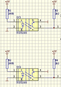
- The sensors are wired as per the diagram below.
- The sensors connect to Pins 2 & 3
- The code below does not use the checkState() interrupt routine.
Do I need to filter the sensors output?
long PulseCount;
long PulseCountOld;

void checkState(){
  // Encoder direction look table
  static int8_t lookup_table[] = {0,1,-1,0,-1,0,0,1,1,0,0,-1,0,1,-1,0};
  static int8_t encoder_value = 0;	//4 bit value (2 left bits = old) (2 right  bits = new)

  encoder_value = encoder_value << 2;	//Shift 2 bits to the left, current vale is moved to old value

  //PIND: 8 bit register holds status of pins 0 to 7 in binary format (Pin sequence:  7,6,5,4,3,2,1,0)
  //The AND comand with mask '1100' keeps the 4 right bits (pins 3,2,1,0) and zeros ou pins 0 and 1
  //The righ shift command moves the values of pins 2 and 3 to the right most position
  encoder_value = encoder_value | ((PIND & 0b1100) >> 2);

  // calculate the index for the look up table (encoder_value & 0b1111)
  PulseCount = PulseCount + lookup_table[encoder_value & 0b1111];
}

void setup() {
  pinMode(2,INPUT);
  pinMode(3,INPUT);
  Serial.begin(9600);
  attachInterrupt(0, checkState, CHANGE);   //get proper command for pin 2
  attachInterrupt(1, checkState, CHANGE);   //get proper command for pin 3

  PulseCount = 0;
}

void loop() {

  if(PulseCount != PulseCountOld)  {
    Serial.print("Pin-2: ");
    Serial.print(digitalRead(2));

    Serial.print("  Pin-3: ");
    Serial.print(digitalRead(3));

    Serial.print("      PulseCount: ");
    Serial.println(PulseCount);

    PulseCountOld = PulseCount;
    delay(500);
  }

}
Hi @salp,
I'll assume you have a multimeter, but not an oscillosope.
I think I would start with just one optosensor detection chain, and a simple piece of card instead of the wheel, so any weird interactions are removed.
I would ensure the resistors R1 to R4 are close to the sensors (in wire length terms) and I would also put some decoupling capacitors across 5V to 0V, near to the sensors and resistors, so that noise from the power lines is minimised. Maybe 100 microFarad electrolytic (watch polarity) and 0.1 microfarad ceramic in parallel.
I might also start with an even simpler program loop, no interrupts. In the "void loop" just a pin input read and an "If" that prints "Card" or "No card" as appropriate, plus maybe a wait of say 100 millisecs to maintain a sensible update rate*, and give time for the line to print.
(*You might wish to pick a higher serial rate than 9600 in your code, and adjust the serial monitor to match. I usually set it to 115200.)
Assuming you have at least a multimeter, whilst watching the "Card/No Card" print on the serial monitor, I would look at the voltage on the output on the output pin (3) of the sensor. I would hope it was approaching 5V with the card blocking (although anything above 3V is probably OK), and comfortably below 0.5V (this is 'more critical') with the card removed.
If this works, and looks ok, replace the card with the wheel, and check the voltages and serial prints etc. are the same.
If it is working now, try reverting to your interrupt code, but initially just with one sensor, etc.
Finally, expand to two sensors, etc.
---------
It is also possible for you to put a capacitor across pins 3 and 4 of the opto sensor to try to filter spikes ... the value would depend on the expected rate of dark and light when it is in 'active' service. Too much capacitance will mean no detection, too little then not enough filtering. However, I would start with the above hints, and treat this as a last resort.
Good luck with you quest!
Dave
Thank you for the detailed reply. You are correct I don't have an oscilloscope, but I dove have multi-meters which I used to test the sensors originally.
I tested with a card before adding the wheel, but I didnt connect it to the Arduino so I dont know if it was bouncing from the start.
I'm going to follow your suggestion and test one loop at a time from scratch and also add the capacitors.
Thank you again,

