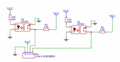
I tried to use one of the online PCB manufacturers "https://jlcpcb.com" but when I got the board I realized the wiring was wrong (my attempt and fixing failed, no comments on my soldering ).
How can I check the wiring before submitting the file to build, or even better does anyone know of an exiting module to purchase. The module is a simple two optical sensors as described in this article convert-dc-motor-into-dc-servo-motor.
Sal
I re-read my post and realized how vague the question was.
The first time I did this I got the wiring wrong so I thought I would post the schematic before placing the order
The schematic is drawn with easyEDA and it shared at Photo Interrupt Module
The schematic you posted is certainly correct in view, whether it will do what you need is not determinable from the information supplied.
Why didn't you just use the schematic from the original article ? Didn't have/want Schmidtt triggers ?
Anything seems possible when you don't know what you're talking about.
@will , I tried to keep soldering to a minimum, also could not get the schematic drawn correctly.
I'm just starting out, so I really do not have much of anything. I'm buying what I need as I go along and get a couple extra.
Frustrating part is I go it to work on the perboard and I seem to mess up on the schematic. Luckily the boards are quite cheap (costs more to ship them).
(PS: I think the pin out of the sensors I used were not the same as the ones in the schematic)
Thanks for the input.
Sal
In your circumstances, you should really be breadboarding the circuits to make sure that they work as you intended. It's a lot faster, cheaper and easier to move around wiring and parts on a board than to keep trying by designing new PCBs.
I'm curious why it worked on the perfboard but not the PCB, did you try making shortcuts while transferring the parts and wie layouts ?
If you're using JLCPCB, then you should probably also be using EasyEDA as the schematic and PCB design tools. They allow you to pass the completed PCB on to JLCPCB by transferring the Gerber files directly and will guide you into the order process.
But don't give up, everybody here struggled in the beginning 🙂
Anything seems possible when you don't know what you're talking about.
Thank you for the encouragement, I really think I got confused with the pin out because I traced all the wire paths and it was almost a mirror of what it should have been. I scratched out the paths on the PC and soldered wires to the proper connections, Before I didnt mention that I got one of the sensors to work after I rewired the board. I'm confident enopugh to give it one more shot.
Thanks for the advice.
By the way I really do not know what the "Schmidtt triggers " do, and since the perfboard mock up worked I figured I dont need them (now I need to go read up on them and see what their function is, great more homework 😊 😊 ).
@salp I'll suggest that if you substitute parts or otherwise adapt a published design, that you understand why your changes are either immaterial to the circuit's function, or better suited to your needs. I'm cueing off you not knowing what Schmitt triggers are and if they really mattered.
To me, the most fun part of a project is doing the analysis of what is, and whether it should be something else - it almost always broadens my understanding. 🙂
Good luck! Looking forward to further updates. 🙂
I edit my posts to fix typos, correct grammar, or improve clarity. On-screen keyboards are evil.
Hi @salp, I am learning to use AutoCAD Eagle (under student license) as my design tool. I've had good luck submitting my board files to Aisler (aisler.net) for fabrication. They support many other software titles too. I usually start by bread boarding my project. Simple circuits, I build on a Proto Board (similar layout to a bread board). If I want more than one, I use Eagle and Aisler. If you have a student email address, you have access to a full suite of AutoDesk products.
ZoolanderMicro, where small ideas are a big deal

