I was on another forum where they do RC aircraft and some subset actually rewind their brushless motors. I asked this question there (and even re-phrased it) and I kept getting an answer involving inductance that I thought I knew from basic EE 101 I took in back in 1980.
I basically want to do the old grade-school experiment of making a electromagnet by winding around a nail and attaching a battery.
Question 1 - If I have a piece of wire, from gauge charts, I should be able to calculate its resistance. Now, if coil it hundreds/thousands of times, I should still have the same resistance as long as I use DC current??? At which point I can just use V=IR calculations.
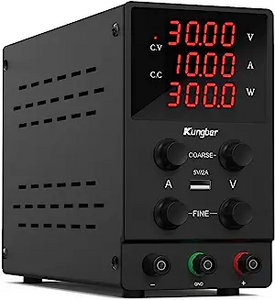
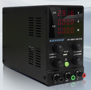
Question 2a & b - If I use a cheap bench power supply along these lines to supply DC power, would it typically be using something like PWM? Would that then start creating Inductance resistance and throw the V=IR calculations out the window?
Thanks.
VBR,
Inq
3 lines of code = InqPortal = Complete IoT, App, Web Server w/ GUI Admin Client, WiFi Manager, Drag & Drop File Manager, OTA, Performance Metrics, Web Socket Comms, Easy App API, All running on ESP8266...
Even usable on ESP-01S - Quickest Start Guide
Hi @inq,
It is likely, though by no means certain as a minority use linear circuits, that the power supply will be based on a switch mode power supply, and switch mode power supplies in turn are based pulse modulation.
(I have avoided using the term pulse WIDTH modulation as there are variations on the way the pulses are modulated, but this is really fine, and largely irrelevant detail to your question.)
Whilst the voltage output of a switch mode power supply is varied by switching the incoming power on and off, this waveform is then passed to an inductor and capacitor based circuit which converts it back to a steady DC output.
Of course, if you look closely enough, there will be a trace of the switching waveform, but the amplitude of this ripple should be at the millivolt level for a "good quality" power supply unit.
I tried looking for a ripple specification for supplies that looked similar to your photo on Banggood and found
which claims: Ripple noise: s30mvrms
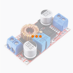
Even the cheap, widely available 'buck regulator' boards are based on the same principles, but the ripple is likely to be higher due to the minimal filtering.
Output ripple: 50mV (maximum) 20M bandwidth
----------------------------
So, although the power supply unit probably uses pulse modulation, unless you are looking at a high precision measurement that can detect the small discrepancy due to the ripple, the basic V=IR Ohm's law should be fine.
Best wishes, Dave
Thank you @davee!
Precision isn't really that important in this experiment. I have 28 gauge motor winding wire coming. I just want to be able to use that chart above giving Ω/Length, given a certain current and voltage, I should be able to calculate the length using V=IR. It being even +/- 10% won't be an issue, but if inductance once wrapped was doubling the resistance, then I'd be kind of hosed.
3 lines of code = InqPortal = Complete IoT, App, Web Server w/ GUI Admin Client, WiFi Manager, Drag & Drop File Manager, OTA, Performance Metrics, Web Socket Comms, Easy App API, All running on ESP8266...
Even usable on ESP-01S - Quickest Start Guide


