Hello! I am a second-year engineering student who has been tasked with creating an RC car. I am using a DC5-12V motor controller to power two 775 DC motors. I am also using a nRf24L01 module to transmit and receive signals.
I tested out my car yesterday and everything seemed to be working well. My code functions as intended, and the car holds up well. However, I am very worried about the reliability of the nRF24L01 chip. I plugged everything in again today and now the receiver Arduino will only receive signals when the transmitter is connected to the USB. I am powering the Arduino nano on both the transmitter and receiver by using a 9V battery connected to Vin and GND. It all worked yesterday but today it doesn't work. Why is this? How can I solve this issue?
I am not sure if this affects anything, but my transmitter is set up like this,
My nRF24L01 chip is plugged into a voltage regulator, CE is connected to 9, CSN is connected to 8, SCK is connected to 13, MOSI is connected to 11, MISO is connected to 12, VCC is connected to 5V on a breadboard, and GND is connected to GND on a breadboard.
From my Arduino I have 5V to the + terminal on the breadboard and GND to the - on the breadboard. I also have two joysticks connected to the + and - terminal on the breadboard.
Am I just not giving the transmitter enough power?
Very likely not enough power. As a rule of thumb, try not to power anything from an MPU or MCU other than things that use just a few ma.
That's about all I can think of given the little information to go on.
First computer 1959. Retired from my own computer company 2004.
Hardware - Expert in 1401, and 360, fairly knowledge in PC plus numerous MPU's and MCU's
Major Languages - Machine language, 360 Macro Assembler, Intel Assembler, PL/I and PL1, Pascal, Basic, C plus numerous job control and scripting languages.
Sure you can learn to be a programmer, it will take the same amount of time for me to learn to be a Doctor.
@zander How should I power it? And could you explain what MPU and MCU are? If that’s the computer I wasn’t planning on using that to power but I have no clue why the 9v isn’t working today. What other information could I give you to help make it easier to help?
@jettedlikeshek First the easy stuff. MPU is Micro-Processor-Unit like a Pi and MCU is Micro-Controller-Unit like an Arduino or ESP board.
Unfortunately you said
VCC is connected to 5V on a breadboard
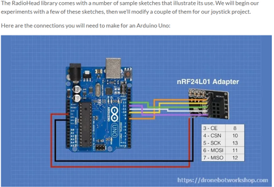
but Bills (dronebot-workshop) said in his video/article that the VCC is NOT 5V tolerant, so you may have ruined the board and who knows what that would do to the battery. See attached pic. This is why I encourage people to read the accompanying article, the video is eye candy but the article is the meat.
What would help is a wiring or circuit diagram. As you are a young fellow, you likely know how to do that, us old timers still use pencil and paper.
I attached a second picture that may explain your battery issue. May I suggest a careful reading of the article? The article can be found at ARTICLE
First computer 1959. Retired from my own computer company 2004.
Hardware - Expert in 1401, and 360, fairly knowledge in PC plus numerous MPU's and MCU's
Major Languages - Machine language, 360 Macro Assembler, Intel Assembler, PL/I and PL1, Pascal, Basic, C plus numerous job control and scripting languages.
Sure you can learn to be a programmer, it will take the same amount of time for me to learn to be a Doctor.
Hi @jettedlikeshek,
It's always difficult to guess what the other person is doing, unless they provide lots of information, which sadly is rare.
As Ron @zander points out above, you need a fair power capability when the chip transmits, not just a few milliAmps.
------------
I notice you speak of Arduino and 5V, which leads me to wonder what voltage you are supplying to the nRD24L01.
However, the nRF24L01 chip cannot handle 5V, as a power source. Furthermore, as the forum's host Bill (@dronebot-workshop) has pointed out, the 3.3 V supply from Arduino and similar boards is usually insufficient, although I might have expected that to affect the USB supply situation as well.
If you haven't already done so, I suggest you read Bill's blog on the device, which discusses its power requirements and how to address the problem. You will notice he also suggests adding decoupling capacitors, which are often forgotten.
https://dronebotworkshop.com/nrf24l01-wireless-joystick/
And make sure the nRF24L01 and the Arduino have a common earth connection, that is still functional.
Good luck with your project and best wishes, Dave
@davee FYI @jettedlikeshek Great minds think alike but of course you mentioned the common grounds.
First computer 1959. Retired from my own computer company 2004.
Hardware - Expert in 1401, and 360, fairly knowledge in PC plus numerous MPU's and MCU's
Major Languages - Machine language, 360 Macro Assembler, Intel Assembler, PL/I and PL1, Pascal, Basic, C plus numerous job control and scripting languages.
Sure you can learn to be a programmer, it will take the same amount of time for me to learn to be a Doctor.
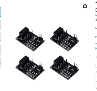
@zander Yes, when I said 5V on breadboard I meant the voltage regulator VCC is plugged into the 5V on the breadboard, not the actual nRf24L01 chip's VCC. Here is the amazon link to the specific regulator I used.
@zander In the article, you gave me, it displays a section labeled nRf24L01 Adapter Module. I am using one of those which I thought would've solved this problem. I also saw a post saying that based on the schematic of the adapter board, the built-in capacitor should be wired to ground. Should I try this?
@jettedlikeshek I think you need to do the work, unless you want to share your engineering degree with me and the others who have/may help you.
The fact that you didn't just google MCU and MPU is quite discouraging. I hate spoon-feeding people, especially those in university who are 60+ years younger.
I think you need to make some progress before getting any more help.
First computer 1959. Retired from my own computer company 2004.
Hardware - Expert in 1401, and 360, fairly knowledge in PC plus numerous MPU's and MCU's
Major Languages - Machine language, 360 Macro Assembler, Intel Assembler, PL/I and PL1, Pascal, Basic, C plus numerous job control and scripting languages.
Sure you can learn to be a programmer, it will take the same amount of time for me to learn to be a Doctor.
@zander My apologies, I have been working on this project for the past 4 months and have been trying everything imaginable. I’m sorry for assuming that maybe I could get more helpful feedback from a forum than just reading through even more articles. Being a second year student means I have way less experience than someone like yourself and I was hoping that instead of blowing through my last adapter board/receiver modules I could get help understanding and hopefully fixing my problem. I have put numerous hours into figuring this out and I don’t want anything given to me. I just wanted to get help as to any possible reasons why it stopped working. With the adapter module and a 9V battery I thought that was enough. Again, I don’t want anything given to me, I apologize for not being clear enough.
@jettedlikeshek No problem, I gave you the information that accounts for the depletion of the 9V battery, did you see it?
I forgot, did you also see the part about NOT using 5V?
First computer 1959. Retired from my own computer company 2004.
Hardware - Expert in 1401, and 360, fairly knowledge in PC plus numerous MPU's and MCU's
Major Languages - Machine language, 360 Macro Assembler, Intel Assembler, PL/I and PL1, Pascal, Basic, C plus numerous job control and scripting languages.
Sure you can learn to be a programmer, it will take the same amount of time for me to learn to be a Doctor.
@jettedlikeshek
Perhaps you could provide a drawing of your wiring to help us understand your circuits.
Anything seems possible when you don't know what you're talking about.
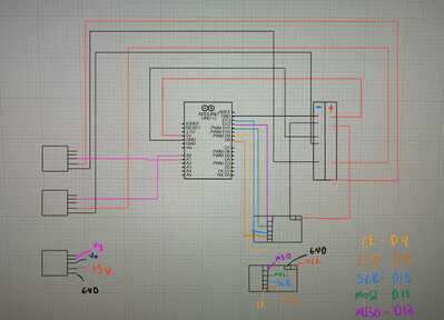
@will Here is a circuit diagram of the transmitter. I apologize for the lack of formatting, I'm a mech so I haven't been around circuits for too long. But, I did my best to make it readable. I am using two joysticks which can be seen to the bottom left, I put a legend type drawing, so you know what pins what are. I did the same for the nRf24L01 Adapter Module. IMG_0173.jpg
I hope I uploaded these correctly after watching the video. But the second image is of the nRf24L01 adapter module that will supply a constant 3.3V to the Nrf24L01 chip. I have experimented with this and when I use the 5V port the nRf24L01 chip transmits and it doesn't work when using the 3.3V pin.
It's difficult to answer your question about power supply when you haven't indicated any power source for either the transmitter or receiver circuit.
Your original post suggests that you're using a 9V battery (one each?) to power both tx and rx circuits but neither is shown on the diagram.
The two unlabelled boxes on the middle left area (motors ? motor drivers ?) are not wired identically but since we don't know what they are we can's comment on whether that's a problem.
I assume that the block at the bottom left is one of the two joysticks but there is nothing to show how it is (they are?) connected to the MCU.
As Davee has pointed out you should have isolation capacitors on AT LEAST both of the motor drivers and both NRF modules.
Anything seems possible when you don't know what you're talking about.


