This may have been addressed here before, but I can't find it. If it has please point me to it.
Furthermore, if this is in the wrong category please move it to the correct category.
I can draw to the OLED in a different project by using the different functions from the Adafruit_GFX.h library along with the Adafruit SSD1331.h and the SPI.h libraries.
What I want to do is to load a bitmap image from a micro SD card and display it on a 0.95 color OLED
Hardware being used
-
Arduino Nano (generic)
-
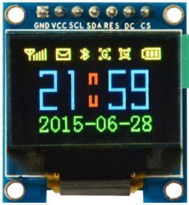
0.95 color SPI OLED that requires the Adafruit SSD1331 OLED Driver Library for Arduino (Adafruit_SSD1331.h) and the Adafruit GFX Library (Adafruit_GFX.h) library.
-
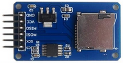
Micro SD Card Module
Hook Up
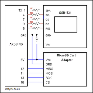
I have the hardware hooked up as seen here but without the resistor on the CS pin. With the resistor on the CS pin, the display is very dim. This hook-up image was included in the sketch mentioned below description.
Code found online
I found this sketch (oled_picture_frame.ino) online at http://moty22.co.uk/sd_bmp.php (ARDUINO SD COLOR OLED PICTURE FRAME) and uploaded it.
Notice that the sketch does not use the two Adifruit libraries.
/*
SD OLED 1331 picture frame
by moty22.co.uk

SD card SPI:
* MOSI - pin 11
* MISO - pin 12
* CLK - pin 13
* CS - pin 10
*/

#include <SPI.h>
#include <SD.h>

#define CS 7 // pins Arduino to TFT
#define DC 9
#define SDA 1
#define SCK 4
#define RST 8

File f1;

void setup() {
pinMode(SDA, OUTPUT); //tft SDA
pinMode(CS, OUTPUT); //tft CS
pinMode(SCK, OUTPUT); //tft SCK
pinMode(RST, OUTPUT); //tft RESET
pinMode(DC, OUTPUT); //tft AO/DC
SD.begin(10);
//TFT USART-SPI
UBRR0 = 0;
UCSR0C = (1<<UMSEL01)|(1<<UMSEL00)|(1<<UCPHA0)|(1<<UCPOL0); // MSPI mode and SPI data mode 3.
UCSR0B = (1<<RXEN0)|(1<<TXEN0); // Enable receiver and transmitter.
UBRR0 = 8; // Set baud rate. must be at the end
oled_init();
}

void loop() {
if(SD.exists("1.bmp")){
f1 = SD.open("1.bmp");
display();
delay(10000);
}

if(SD.exists("2.bmp")){
f1 = SD.open("2.bmp");
display();
delay(10000);
}

if(SD.exists("3.bmp")){
f1 = SD.open("3.bmp");
display();
delay(10000);
}

if(SD.exists("4.bmp")){
f1 = SD.open("4.bmp");
display();
delay(10000);
}
if(SD.exists("5.bmp")){
f1 = SD.open("5.bmp");
display();
delay(10000);

}

if(SD.exists("6.bmp")){
f1 = SD.open("6.bmp");
display();
delay(10000);
}
}

void display(){
unsigned int i=0;
unsigned char c;
command(0x15); // Column addr set
command(0);
command(95);
command(0x75); // row addr set
command(0);
command(63);
while (f1.available()) {
++i;
c=f1.read();
if(i>67){send_data(c);}
}
f1.close();
}

unsigned char spi(unsigned char data) // send character over spi - talking
{
while ( !( UCSR0A & (1<<UDRE0)) ); /* Wait for empty transmit buffer */
UDR0 = data; /* Put data into buffer, sends the data */
while ( !(UCSR0A & (1<<RXC0)) ); /* Wait for data to be received */
return UDR0; /* return received data from buffer */
}

void command(unsigned char cmd)
{
digitalWrite(DC, LOW); // Command Mode
digitalWrite(CS, LOW); // Select the LCD (active low)
spi(cmd); // set up data on bus
digitalWrite(CS, HIGH); // Deselect LCD (active low)
}

void send_data(unsigned char data)
{
digitalWrite(DC, HIGH); // data mode
digitalWrite(CS, LOW); // chip selected
spi(data); // set up data on bus
digitalWrite(CS, HIGH); // deselect chip
}

void send_color(unsigned int color)
{
send_data(color>>8);
send_data(color);
}

void oled_init(void)
{
unsigned char i;
digitalWrite(RST, HIGH); //hardware reset
delay(200);
digitalWrite(RST, LOW);
delay(10);
digitalWrite(RST, HIGH);
delay(10);
command(0xAE); //display off
command(0xA0); //remap
command(0x72); //RGB=0x72, BGR=0x76, 24bits=B2 A2=fliped (0b10100010)
command(0xA1); // CMD STARTLINE
command(0x0);
command(0xA2); // CMD DISPLAYOFFSET
command(0x0);
command(0xA4); // CMD NORMALDISPLAY
command(0xA8); // CMD SETMULTIPLEX
command(0x3F); // 0x3F 1/64 duty
command(0xAD); // CMD SETMASTER
command(0x8E);
command(0xB0); // CMD POWERMODE
command(0x0B);
command(0xB1); // CMD PRECHARGE
command(0x31);
command(0xB3); // CMD CLOCKDIV
command(0xF0); // 7:4 = Oscillator Frequency, 3:0 = CLK Div Ratio
// (A[3:0]+1 = 1..16)
command(0x8A); // CMD PRECHARGEA
command(0x64);
command(0x8B); // CMD PRECHARGEB
command(0x78);
command(0x8C); // CMD PRECHARGEC
command(0x64);
command(0xBB); // CMD PRECHARGELEVEL
command(0x3A);
command(0xBE); // CMD VCOMH
command(0x3E);
command(0x87); // CMD MASTERCURRENT 06
command(0x15);
// command(0x81); // CMD CONTRASTA 91
// command(0xFF);
// command(0x82); // CMD CONTRASTB 50
// command(0xFF);
// command(0x83); // CMD CONTRASTC 7D
// command(0xFF);
//command(0xA4); //Normal display on
command(0xAF); //Main screen turn on
}
It draws the bitmap (I have only one) and instantly clears the screen. There is a ten-second delay (delay(10000)) within every if statement inside the void loop() so there's a black display. When I commented out the delay at line 53 the image keeps reloading which I had expected.
The sketch was written to be a slide show and that is fine.
Maybe Bill will do a video on this topic.
Maxairedale


