I am learning to solder with some electronic kits after watching a lot of YouTube videos on the topic.
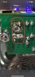
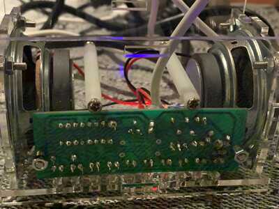
While the videos have been useful, I can’t figure out why the soldering of the power wires to the PCB ended up with such a messy solder joint compared to the rest of solder joints I made (which you can also see in picture).
Solder was same one used for other joints and solder station was at stable 350C. Photo via link:
Any insights from those with experience?
removed link
I'm sorry, but with the new forum policies, you won't be able to add a link to your post until you have made three posts. But you can always just drag the picture into the post!
😎
Bill
"Never trust a computer you can’t throw out a window." — Steve Wozniak
Hi Bill,
The problem is that your server seems to prevent adding attachments. It says; “No more attachments are allowed today”
This is an attempt to share the photo that I was referring to above. I tried to attach it with a URL and it got rejected as I am new to the forum. Then I tried using the attachment button but the forum displays 'No more attachments are allowed today'. I am testing now testing to see if drag and drop of photo works.
P.S - Would be nice to have a way to post pictures from mobile phone as 'draft and drop' is not possible on mobile.
@witschey We have had issues over the last few days of someone hacking into the forum and posting inappropriate links and attachments, so Bill had to up the "moderation? flag to a higher number of posts. Your last three posts were in "moderation" until just a few minutes ago. Once you get a few more posts you should be fine.
What kind of solder are you using? Those joints look like cold solder joints to me. A larger gauge wire than just a component lead will wick away some of the iron's heat and may need the heat applied longer. Do you have a photo of what the solder pads looked like before soldering? What is the gauge of the wire?
Replying to me will put another post in you post count.
SteveG
@witschey That needs more heat, and some resin would also help. I use liquid with a needle dispenser and my temp is 700F/370C. I use a small bevel tip for most work but have a dozen other tips if needed and a much cheaper older design big brute for heating ground planes and other larger parts.
EDIT:
Just went back and looked closer. That will need one of the bigger bevel tips. Conical and pointed tips do not bring enough heat, you need a moderatly flat surface that the bevel gives you. I almost always use bevel tips now especially for surface mount but even through hole. If some liquid flux and a hotter big bevel don't clean that up in a couple seconds, clean that area with solder wick first and try again. Do not use lower heat for longer time, you risk raising the traces off the board. Hot and fast is the ticket and flux makes it 10 times faster.
First computer 1959. Retired from my own computer company 2004.
Hardware - Expert in 1401, and 360, fairly knowledge in PC plus numerous MPU's and MCU's
Major Languages - Machine language, 360 Macro Assembler, Intel Assembler, PL/I and PL1, Pascal, Basic, C plus numerous job control and scripting languages.
My personal scorecard is now 1 PC hardware fix (circa 1982), 1 open source fix (at age 82), and 2 zero day bugs in a major OS.
@codecage Thanks for the reply.
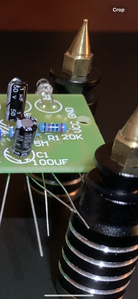
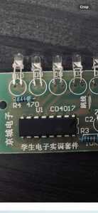
Unfortunately I don't have a photo of the solder pad side of the PBC ,but here is a photo of the other side of the PCB before I began soldering.
The two homes with the 'mess' are the VCC and GND holes that you see to the right. While I don't know the wire gauge it was thinner than the jumper cables used for an arduino. I peeled about half an inch of the plastic cover and applied solder onto them before passing them through the PCB hole and attempting to solder, but when I applied the solder (hoping it would react like it did with all the other electronic components I soldered) it turned into that big mess and the threads of the wire lost the solder cover I had put on them and became mushi which is why I ended up with that blob of wire mixed with solder.
Those were the two last two things I needed to soder to the PCB.
As you can see from this second picture the rest of it soldered OK (although I think a bit bigger than it should have been).
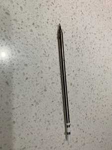
However one additional element that may shed some light as to the possible cause of the mess, is that the Iron Tip I used stopped working well after I finished. I tried to apply a new coat of solder onto the tip and it just slides off. It doesn't seem to heat the solder well anymore (breaks into pieces when I try to heat it up - even if I use a new reel). I have read that perhaps I damaged the tip by not applying a coat of solder every single time I used it. However I didn't realise I had to do that every single dot of solder I applied (is that what I need to do)?
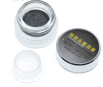
Tried to clean it up with 'Iron Tip Head Refresher' but while it visibly cleans it, I can't get the solder to stick on it. So I think its dead. No big deal as I realise that learning has a price, but I wish I knew what I need to do to prevent this from being the outcome I get after every single day of soldering...or it will get expensive.
@zander Hi Zander,
I am using Mixed Tin Rosin Core Solder and this type of Rosin.
Frankly I am not sure how to apply this rosin because it is hard as a rock when cold. So what I have been doing is dipping the tip of the iron into it when hot and then trying to put some of it on the PCB but that doesn't work well. I have now ordered the syringe liquid time (Amtech 559).
The type of PCBs that I am working on right now are hole PCBs like the one shown below. The metal pads are not very big. In fact with my eye sight not being that great anymore, I have to use magnifying glasses or a digital microscope to solder onto them.
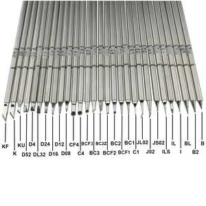
Of the iron type types shown in the picture below, which model number would you use for the above PCB soldering job?
Thanks in advance for any tips you can share.
Paul
@witschey That resin is for something else, at best tip cleaning.
I would use D24 or maybe D16, it's a litt. Larger to the left, and smaller to the right.
Also, if you know how to do drag soldering on say a IC, then the tips BC2 and BCF2 (finer) if hollow (or cows foot) will hold a blob of solder that you then drag apply across a row of pins/tabs etc. Lay down some liquid solder first and it just flies on. Great for headers on MCUs etc.
First computer 1959. Retired from my own computer company 2004.
Hardware - Expert in 1401, and 360, fairly knowledge in PC plus numerous MPU's and MCU's
Major Languages - Machine language, 360 Macro Assembler, Intel Assembler, PL/I and PL1, Pascal, Basic, C plus numerous job control and scripting languages.
My personal scorecard is now 1 PC hardware fix (circa 1982), 1 open source fix (at age 82), and 2 zero day bugs in a major OS.
@witschey As far as your 'dead' tip. I assume you have steel/bronze wool, insert the tip in that every time the iron comes out or goes into the cradle. A small tin of solder paste and an even smaller tin of 'Tip Tinner' should be part of your kit. I do not think that a wet sponge is good practice, it causes thermal shock in the tip.
If I am going to do a lot of soldering, I will immerse the tip in the paste and rotate it to get full coverage and then clean it in the steel wool. Now a small application of Tip Tinner again rotate the tip to get full coverage. After that as I said, every time the iron goes in or out of the cradle, stick it in the steel/bronze wool.
If soldering every day, maybe once a week do the tip cleaning again.
First computer 1959. Retired from my own computer company 2004.
Hardware - Expert in 1401, and 360, fairly knowledge in PC plus numerous MPU's and MCU's
Major Languages - Machine language, 360 Macro Assembler, Intel Assembler, PL/I and PL1, Pascal, Basic, C plus numerous job control and scripting languages.
My personal scorecard is now 1 PC hardware fix (circa 1982), 1 open source fix (at age 82), and 2 zero day bugs in a major OS.
Hi @witschey,
Having gone through what you’re going through I thought that I’d chime in. Sharing is Caring, right?
I echo what @codecage said about the picture looking like cold solder joints. I’ve found that a lot of PCB designers use copper zones to tie grounds and power connections together, something about having lower impedance than traces. This is great for the board but a pain for us because the area that the soldering iron heats up is now very large. As an aside, I noticed that soldering headers to the GND pins of the RPi Pico never gave me any problems, but the Pico-W takes more time and heat to get the job done.
Did you determine what gauge wire you are using for those connections?
Those tips look huge, what soldering station are you using? In my case I’m using an inexpensive 30 Watt pencil iron with no temperature read out. It’s taken some trial and error to find the right settings. For through hole components and header pins I use a 1/32” semi-chisel tip with 0.025” rosen core solder. I started with leaded solder as it is supposedly easier to use… Recently I started soldering SMD components and for that I use a 1/64” conical tip and 0.3mm lead-free solder.
I recently ruined a soldering tip so that it no longer holds solder :/ It was a non-OEM tip, the only one I could find on-line, and I must have gotten it too hot. I was tinning it constantly so that wasn’t it. Luckily I bought two at the time so I’m using the second one but the temperature is not ideal (cold joints on GND connections). I need to upgrade my kit!
That block of rosen reminds me of High School metal shop where we soldered together small boxes made from sheet metal. Those soldering irons where huge. As you progress you might want to pick up some flux, either liquid or paste. To clean up that mess on your board you can get some solder wick, soak it with flux and use your iron to melt it into the wick.
I would not recommend drag soldering. Check out MrSolderFix on YouTube when you get around to making your own PCBs and want to solder ICs.
The cold joints need more time under the soldering iron and possibly more heat. If it were me I’d probably try soldering the same gauge wire to some scrape proto-board to make sure I haven’t set the iron too hot… Excelsior.
Tom
To err is human.
To really foul up, use a computer.
Hi @thrandell, thanks for sharing your experience and providing me with some tips.
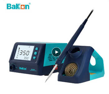
To answer some of your questions. The solder station that I am using is the blue Balkon one shown in the picture. Its great as it keeps the temperature steady. It has a pretty large LCD display that allows you to set the temperature you want and also shows you the temperature tip you have achieved.
As I type this I just remembered that when I was soldering those two last joints the temperature display did jump at some point to over 400C just for a little while; which I found strange as it hadn't happened before.
It uses the standard length T-12 irons that I posted earlier. They basically slide into the handle leaving only a portion exposed.
I also have a Fnirsi digital smart pen like the one shown below that uses shorter T-12 irons, but I haven't started using that one yet as the tips are more expensive (so I want to make sure I know what I am doing before I risk damaging that one).
Yes, I need to learn how to clean the PCB board after soldering. The interesting thing is that it was fairly clean until the moment when I began trying to 'fix' some of the joints that I didn't think were good enough.
I had a few solder dots that were too close together and I was afraid that they might be touching each other. So I tried using solder wick to remove the solder, but I couldn't get it to get hot enough like I see in the youtube videos. Based on the posts in this thread, I believe it was most likely because of the small tip I was using. So I had to leave the tip on it for a long long time before it started to absorb some of the solder and then it got stuck to the board, etc. So I started using flux, but since I only had that solid one I soaked the tip into it and tried to move some of the liquid to the board; but obviously it got hard on the board when it cooled off.
To remove the solidified flux after I had finished I remembered seeing that alcohol was used in youtube videos; but there was so much of that solid flux that the alcohol just didn't get rid of it all. As mentioned earlier, that is not the right type of flux for spreading on the board. My recent readings on it suggest that it is only for the purposes of coating the tip to enhance the soldering process, but not meant to be used on the board itself as a liquid.
As to the wire guage size, I have no idea. Its the wires that came with the kit and they are slightly thinner than the ones used on arduino boards. So pretty thin.
Thanks again for sharing.
Paul
Hi @zander,
Thanks for sharing your insights and for the tips.
I used this tip tinner to try to 'revive' my iron solder, but while it certainly cleaned the iron it didn't revide it.
Regarding the Tip Tinner; is it normal for the Tip Tinner Powder to cristalize and get hard after touching the iron? Do I need to throw away the the hardened (cristalized) Tip Tinner, or do you keep on using it?
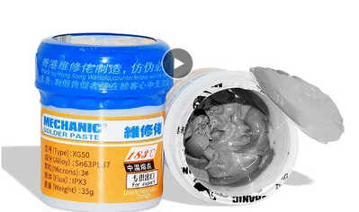
I did not have solder paste in my kit, so I have ordered the one shown below. Is that the type of solder paste you were referring to?
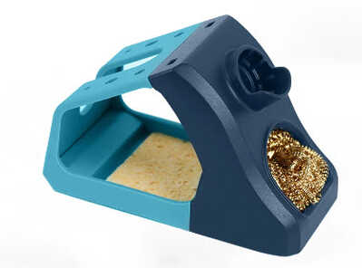
As to the cleaning the tip with the steel / bronze wool every time it goes in or out of the cradle, I am using the one that came with the solder station, which you can see below. Is that what you meant?
Thanks again for your tips and I look forward to your reply
Paul
@witschey My Tip Tinner is a paste, no idea what that is. Your paste looks weird as well. I only use the liquid resin now.
Yes that is the cradle I referred to.
I don't know how a tip can 'go bad' can you explain a bit more, does the tip get hot, does it melt the solder. I think you said the melted solder does not adhere to the tip, is that correct?
First computer 1959. Retired from my own computer company 2004.
Hardware - Expert in 1401, and 360, fairly knowledge in PC plus numerous MPU's and MCU's
Major Languages - Machine language, 360 Macro Assembler, Intel Assembler, PL/I and PL1, Pascal, Basic, C plus numerous job control and scripting languages.
My personal scorecard is now 1 PC hardware fix (circa 1982), 1 open source fix (at age 82), and 2 zero day bugs in a major OS.
Hi @zander ,
Thanks a lot for giving me your oppinion on what tip model to use for this type of PCB job.
I had tried to interpret the right size from soldering videos and articles, but I had obviously misinterpreated as I have been BL and BC1 tips, which are smaller than what you suggest.
I have ordered the ones you suggested to check them out. Fingers crossed!
Paul

