Widget Weight Counter using HX711 and LED Display – Feasibility Study
March 2024
This study was inspired by a new forum member Bill, who registered as @billinfl, and asked for some assistance with his first project. https://forum.dronebotworkshop.com/help-wanted/need-help-with-first-project/#post-46250
Some aspects of this project are already discussed in the thread just referenced, and the reader is advised to look through it for a fuller understanding of the issues.
This project concept consists of a weighing scale, using a strain gauge sensor, and a display single digit large LED. The scale units to be displayed are ‘widgets’, where a ‘widget’ weighs about 6oz (170g), and will always be in the range 0..9. (i.e. it is a ‘Widget Counter’). For ergonomic reasons, the seven-segment LED used for the display is 3” high, with correspondingly higher voltage and current requirements than the ‘conventional’ seven-segment LED displays commonly found in instrumentation, etc.
As this was Bill’s first project, I hoped it would be helpful if I tried to do a very rough prototype and reported on my findings, including some very crude software code, to initially ‘animate’ the hardware. The result is a long way from a ‘finished’ project, with several issues still to be addressed, but I hopefully provides a skeleton framework to get started.
This study is entirely based upon parts I already had in my “junk store”, including some previous ‘impulse’ purchases from AliExpress, that I thought might be interesting, but had never connected up. Hence, they should not be regarded as ‘recommendations’ for a planned project, as alternatives may have advantages, and some are mentioned in the following text. (I am grateful to Louis - @inst_tech for some excellent alternative suggestions.)
Similarly, the programs attached are quick and raw ‘hacks’ as a starting point, with parts grabbed and adapted from Github. They are not examples of ‘good code’, nor are they intended to be.
The test used a 50kg load cell that only produced a small signal with the available loads of up to 2-3kg, which together with the crude mechanical mounting arrangement, showed some propensity to drifts. These drift errors occasionally resulted in the widget count being in error. It is to be hoped that this will not be an issue when an appropriate load cell is used, etc., but presently, drift errors remain an unaddressed risk.
--------------------
Development Strategy
As this is an experimental/development project, I divided it into the following ‘phases’:
- Microcontroller + ‘small’ seven segment LED digit. Hardware design to be able to accommodate LED drive voltages, up to at least 15V. Write test code to show it displaying digits 0..9 in a timed sequence.
- Experimentally add up to 3 discrete LEDs in series with one of the segments, to demonstrate the circuit built in part 1., could handle the higher voltage required for a 3” LED display. (This modification was not retained for the subsequent phases.)
- Wire the microcontroller to the HX711 strain gauge amplifier/analogue to digital converter + strain gauge, plus make a crude mounting for strain gauge.
- Compile test code to extract data from HX711, and display it on the Serial Monitor part of the Arduino development environment. The first programme, calibrate2, is used to determine the scaling factor. (e.g. 42.6317
- Compile a second program, which uses the scaling factor, and also the weight of a widget, to determine the number of widgets in the pan. Results are printed on Serial Monitor.
- Integrate phases 1. and 5. , to obtain a ‘bench level’ prototype of the project.
Phase 1: Microcontroller + ‘small’ segment LED digit
Louis @inst-tech thoughtfully suggested using a SN7446 seven-segment driver, but unfortunately, I didn’t have one in in my store, and I was reluctant to start ordering parts, when I already had an alternative, albeit one requiring a little extra software and 3 extra GPIO pins on the microcontroller.
If any reader wishes to substitute the SN7446, I hope the necessary changes will be obvious, and this report will still be useful. (Please note that the SN7446 requires 5V logic drive, so that the microcontroller must be 5V logic, or a 3.3V to 5V logic conversion added if the microcontroller is 3.3V.)
Louis has also suggested the Texas Instrument TLC5916. A quick glance at the data sheet suggests this would be a good choice for a ‘professional’ product, as it offers a lot of flexibility, internal current control, and only needs a minimal number of the microcontroller’s GPIO ports. This appears to be a good choice for someone who is experienced in handling shift registers, plus programming for brightness, etc. I am slightly concerned that someone undertaking their first project, with only limited test equipment, might make a simple error, and then struggle to diagnose the problem, but this maybe being over cautious.
---
The LED driver chip I chose is a ULN 2003, consisting of 7 Darlington pair drivers in a 16-pin DIL package. It is widely available for less than a US dollar each, albeit often sold in packs of 5 or 10. It’s output current capacity is up to 500mA per driver, output voltage up to 50V, and has the ‘easily met’ requirements of ‘actual’ high output voltage from the microcontroller of at least 3V, and the LED current per segment less than 300 mA. Thus the ULN2003 is generally compatible with both 3.3V and 5V microcontroller GPIO outputs.
Because the ULN2003 is essentially 7 small amplifiers, the input and output levels are directly related, and can be checked with a multimeter, making it easier to diagnose problems. The chip is also generously specified in terms in terms of voltage and current, so should be robust enough to match almost any seven segment, common anode, LED display, including 'large' ones with multiple LEDs in series for each segment. It is also available through AliExpress, Amazon, etc, in 16-pin DIL package, making direct wiring easy, without resorting to surface mount adapters, etc. The obvious disadvantage is that it requires 7 microcontroller GPIO pins to control seven segments, as it does not contain any shift registers or logic.
Notes:
Although the ULN2003 inputs are compatible with both 3.3V and 5V logic, the power voltage is chosen to match the LED display, and would probably be 12-15V for the 3” display.
The ULN2003 has only 7 drivers, whilst driving the decimal point would require an eighth driver. The decimal point was not required for the instigating project.
---------
The display used for this test was a ‘small’ seven segment LED digit, with common anode connection. Hence, it is essentially the same as the 3” display identified by Bill, except the voltage and current requirements are lower, and the current limiting resistors in series with each segment are of a higher value.
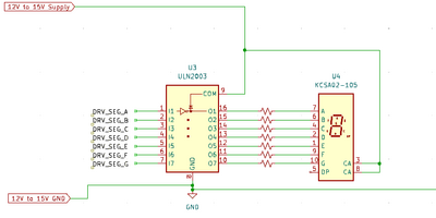
The wiring between the ULN2003 and a seven-segment, common anode LED is shown in the sketch below.
ULN2003 & LED Display wiring (click sketch to enlarge)
Note the GND wiring links to the GND connections for the microcontroller and the HX711, but this sketch shows the only part of the circuit requiring the higher (+12V to +15V) supply for the larger LED display.
--------------------------------------------------------------------
A ‘generic’ ESP32-S3 development board with 42 0.1” pitch pins was conveniently available for this study. The actual requirement is 7 GPIO output pins for the seven segments, plus one GPIO output and one GPIO input for the HX711 (discussed in Phase 3.). Thus the development board needs 9 free GPIO pins, and many lower specification boards would also be suitable.
AliExpress offers ESP development boards from around 2-3 US dollars each (plus delivery). They are also widely available from other sources, which may be more convenient, albeit maybe at a higher price. AliExpress also offer boards described as ‘Nano’ at nearer 1 US dollar, presumably suggesting they emulate the similarly named Arduino board, but as I don’t have one, I haven’t tried it, and I can only suggest it for consideration.
-----
The particular ESP32-S3 board used was powered with 5V, and provided a 3.3V output pin (labelled Vcc), which was used to power the HX711 in Phase 3. Some boards might label the pin 3.3V, and confusingly use Vcc elsewhere, so check the voltage before using this pin for the HX711!
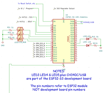
The following sketch illustrates the wiring for the microcontroller chose for the prototype.
ESP32-S3 Development Board wiring sketch
Note that this particular development board came with 5 LEDs, labelled LED3, LED4 & LED5, connected to GPIOs 5, 6, 38 and 39, plus other GPIO pins, including IO0, and IO35-37 are given ‘pre-assigned’ roles. Similar pre-assignments occur with all of the common development boards. Whilst it is sometimes possible to use or ‘free’ some of these pins for another use, the simplest and safest strategy is to only use the ‘totally unassigned’ pins to interface with your project circuit. Unfortunately, locating the pre-assigned pins can sometimes be a challenge. Some will be connected to other components, such as LEDs, but others may be assigned in the bootstrap software that is preloaded before the boards are delivered, and is not usually overwritten when user software is loaded.
------
For this prototype exercise, IO8 through to IO14, were allocated to drive the inputs to the ULN 2003, plus IO3 and IO4 for the HX711 interface, described in Phase 3. For any other development board type, the GPIO numbers can be reassigned, providing the values in the software are changed to match.
-----------------------------------------------------------------------------
For the prototype exercise, The ESP32-S3 board was powered at 5V via the USB connection also used for programming and Serial Monitor communications.
For the final product, after the ESP32 or equivalent processor has been programmed, it is suggested that a small ‘buck' regulator, capable of reducing the 12-15V power to about 7V is added. (The exact output voltage depends upon the power requirement of the microcontroller development board chosen.) For maximum flexibility, ensure the output current capability of the regulator is at least 1 A, although the usual current will be very much less.
A variable voltage source, of up to 15V powered the ULN2003 & LED Display for this exercise, but an appropriately chosen, fixed voltage source should be fine for the final product.
-------------------------------------------------------------------------------
The software programme sevenSegLEDtest1.ino (attached below) is very simple, principally consisting of one function, shownum(int x), which is to be called with the required digit as the parameter x. x is used as an array row select for the segments to be lit.
The main loop repeatedly calls shownum(x) with incrementing values of x.
As the code was aimed for test purposes, it includes options for printing to the Serial Monitor, etc.
Before compiling and running the program, examine, and if necessary edit the #defines near the start of the file sevenSegLEDtest1.ino
#define BAUDRATE 57600 ---- adjust to your preferred Serial Monitor rate
#define SEGA 8 --- Adjust the ‘8’ to match the GPIO pin responsible for driving segment A
#define SEGB 9 .. #define SEGG 14 --- Adjust in similar manner to SEGA, for each segment and corresponding GPIO drive pin
-----
For a ‘Hex to Seven-Segment’ chip, like the SN74LS47 or SN7446, a similar approach would work, albeit converting to the required 4-bit code, (instead of 7-bit code,) should work.
-----
Chips like the TLC5916, with shift registers, etc. will require a little extra coding, but it should still be possible to create a single function interface like shownum(x).
---------------------------------------------------------------------------
Phase 2: Higher Voltage LED Display test
This was an experimental phase to check usage with a segment consisting of 4 segments in series, which was expected to be similar to the 3” LED display. This has been discussed in the thread, so for here, I just repeat the main conclusions:
- I would advise a power source of at least 12V, possibly up to 15V. Obviously, adjust the segment series resistors accordingly. Even larger displays may require correspondingly higher voltages
- For the final unit, add in a buck regulator, to reduce this voltage to about 7V, if microcontroller is 5V logic, or 5V, if microcontroller is 3.3V logic
---------------------------------------------------------------------------------
Phase 3: Microcontroller + HX711 strain gauge amplifier/analogue-to-digital converter + strain gauge + crude mounting for strain gauge
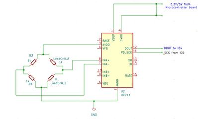
The wiring between the microcontroller and the HX711 principally consists of 4 connections:
- +x V supply, where x= 3.3 or 5.0V, to match the logic voltage of the microcontroller. For the test, this was taken from the appropriate output pin on the microcontroller board. It is possible that a separate linear regulator providing a 'private' supply for the HX711 would improve performance, by reducing noise, is beyond the scope of this study, but that can be tested later as part of the 'product refinement' phase.
- GND on the microcontroller board to DGND on the HX711 board
- DOUT on HX711 board to a GPIO pin IO4, set to digital input on microcontroller board
- SCLK on HX711 board to a GPIO pin IO3, set to digital output on microcontroller board
These are illustrated on the microcontroller diagram above and this HX711 sketch below.
The wiring between the strain gauge and the HX711 board depends on the chosen strain gauge. For my test, the only sensor I had was a single 50kg device, normally used as one of a set of four, in bathroom scales.
See https://learn.sparkfun.com/tutorials/load-cell-amplifier-hx711-breakout-hookup-guide for a description of the wiring options with different load cells, etc.
----
Clearly, the strain gauge device I used would be a poor choice for counting widgets weighing only 6 oz. (0.17 kg) each. Nevertheless, I did manage to ‘count’ units of 0.6 kg, so I would hope a strain gauge with a more suitable range would work reliably.
The load cells consisting of a beam with the strain gauge at a 'weakened' point in the middle of the beam would be a far better choice.
-----
Sparkfun have their own HX711 board design (coloured red), which from the advert appers to offer some improvements, compared to the HX711 board I used, which was green in colour. Whether those improvements would usefully improve this design, which has only 1 digit resolution, would also be part of later 'refinement phase'.
The ‘green board’ style is widely advertised on the web, although it is plausible the there are many different manufacturers offering roughly the same thing. They look similar to the product offered at:
https://www.creatroninc.com/product/hx711-load-cell-amplifier/
This web page also includes a link to a schematic of the board at
My initial investigations with this board showed ‘unexpected’ voltages, so I did a web search, which resulted in the discovery of discussions about the GND connections, that are a little more complicated than might be expected. The generic design in the HX711 data sheet from
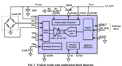
https://www.digikey.co.uk/htmldatasheets/production/1836471/0/0/1/hx711.html is:
HX711 Data Sheet 'Typical weigh scale application block diagram
The diagram shows 7 triangle GND symbols, suggesting they should all be connected together, whilst the “Green PCB” splits them into two groups, Analogue Ground and Digital Ground.
I am not aware of any ‘official’ documentation to accompany the “Green PCB” design, so I speculate that the split is designed to match to a star point grounding scheme, to minimise pick up of digital noise, with individual connections from the E- pin and the GND to the star point. It seems clear that the E-pin and the GND pin should be connected together.
For my simple test, E- was connected to GND with a short wire link, but a better ground wiring strategy for a final product might improve the weighing performance. This is a further 'product refinement' point to consider.
-----------------------------------------------------------------------------
For a minimal, mechanical arrangement of the load cell, a new drawing and 3D model was created, based on the same principle as https://www.thingiverse.com/thing:4702561
It is presumed that a 'beam' shaped load cell would be used in other studies, so this comment is just to complete this report.
-----------------------------------------------------------------------------
Phase 4: Calibration “calibrate2” test programme
This is based on the “Arduino HX711 Library by Bogdan Necula, including the instructions at
https://github.com/bogde/HX711
This code is used to find the division factor required to convert the voltage reading from the HX711 into a weight, based on the voltage measured with a known weight on the pan.
Before compiling and running the code, check all of the #defines near the start, and edit appropriately.
• #define BAUDRATE 57600 --- Serial Monitor Baud Rate
• #define LOADCELL_DOUT_PIN 4 --- GPIO connected to HX711 DOUT
• #define LOADCELL_SCK_PIN 3 --- GPIO connected to HX711 SCLK
• #define CALIBRATION_WEIGHT 2495.0 --- Weight of calibration object
Note the Weight of the calibration object can be in any units, e.g. g, oz, kg, lb … this study used 2495 (g)
Then:
- Ensure Serial Monitor window is visible
- Boot the program with an empty pan.
- Place calibration weight on pan when prompted
- Click in the Serial Monitor Message window, and type an ‘a’, followed by the Enter/Return key
- Note the set_scale() calibration value printed by the programme .. e.g. 42.631
- Remove the calibration weight from the pan
- Enter ‘a’ + Enter, as before
- The calibration value will then be used for further weight measurements, but only whilst the program continues to run.
------------------------------------------------------------------------
Phase 5: Program WeightWidgetCounter is derived from Calibrate2
The previously determined scale factor is compiled into the code, and the Serial Monitor printout is extended to display the number of widgets in the pan.
Before compiling and running the program, check and edit all of the #define statements near the start of the code, as before.
The two new lines are:
#define WIDGET_WEIGHT 625.0 --- this is weight of a single widget
#define SET_SCALE PARAMETER 42.0 --- this is the scale factor printed out by Calibrate2
The resulting program should display the actual weight and widget count on the Serial Monitor.
------------------------------------------------------------------------
Phase 6: Programme WidgetWeightCounter2
This adds the LED driver code used in Phase 1, (with slight modifications) to the Phase 5 Weighing and Counting capability, so that the number of widgets in the pan is also shown on the LED display.
Note the two files (named below), must be in the same folder, named WidgetWeightCounter2, and both should appear as ‘tabs’ in the Arduino IDE
Once again, before compiling and running the program:
All of the #defines near the start of WidgetWeightCounter2.ino should be checked and edited.
In addition, the accompanying sevenSegLEDtest2.ino file should be examined, to ensure all of the #defines near the start of the file are correctly set.
-------------------------------------------------------------------
Hopefully, the first bench prototype is now demonstrating the basic required functionality!
However, it will be far from ‘perfect’. Expect to do a lot of ‘fine tuning’ for the best results.
------------------------------------------------------------------
Attached programmes:
1. Phase 1: sevenSegLEDtest1.ino
2. Phase 4: calibrate2.ino
3. Phase 5: WidgetWeightCounter.ino
4. Phase 6: WidgetWeightCounter2.ino + sevenSegLEDtest2.ino
-------------------------------------------------------------------------
Dave, All I can say is, WOW! The time and effort you have invested here, with no compensation on the horizon, (that is, until I figure out how to send you a case of your favorite "whatever",lol), is almost shocking. I'm feeling like "Thanks" doesn't really say enough, but here's 10 more, and that's just for today. I can't comment on any of the technical info you provided, since it is all above my (current) pay grade, but I do want to mention that I'm a little apprehensive about what lies ahead with regards to (my part of) completion of the project. In my minds eye, I see a situation similar to one of those classic movies where the pilot of the plane is sick or dead, and a passenger has to land the plane, with instructions over the radio. (Well, not that bad, since I do have limited experience working on electrical things, including detailed wiring and soldering, but nothing to this level). So, it will be more like they found a passenger who has flown a two seater Piper Cub, but will now land the 747. I'm definitely up for it, and I love a challenge, but I foresee quite a bit of (long distance) hand-holding, so I'm just putting that out there. For example, in your Phase 1:Microcontroller section, you say that Louis' suggestion (thanks Louis) of the TLC5916 would be a good choice for someone who is experienced in handling shift registers, programming for brightness, etc, are things I will be doing for the first time. Also, the lack of (required?) test equipment is mentioned, and yes, I am limited to two (count em') pieces of equipment, (Fluke 117, and 325), unless of course we are going to count my trusty old Simpson 260, but that's from another life. Lastly, I do have a couple of operational questions, and please forgive me if I'm putting the cart before the horse, considering that you're still working hard at just getting a prototype up and running. The questions I have concern the ongoing operation of the system, which, in a perfect world, would be able to run continuously 24/7/365 once both systems are energized, and the initial weight calibrations are done. Once the display(s) are showing a number from zero through nine, would I just be able to "slowly back out of the room" and that's that? (I just remembered something that I may not have mentioned before. With regard to the number of widgets in the pan, there are times when the number of widgets will be reduced, usually by one, but sometimes two, by manually removing them from the pan. Will the system be able to be coded so as to account for the times that widgets are both increased AND decreased? Ideally, the readout will always be "live", showing the current count, whether widgets are dumped in or pulled out. Sorry if I failed to mention that before!) Finally, with regard to continuous operation, the readouts won't actually be used 24/7, but I only mentioned that because I'm concerned that powering down the system will lead to having to reset and recalibrate, which, because of the mounting situation, is just a pita. I'm not sure where you stand on the matter of these microprocessor systems running all the time. Another matter is that with so many storms here in the summer, there will be power losses, which I assume would lead to restarts/boots. In an effort to possibly eliminate those power glitches, I have researched UPS units that are available for not much, and would(?) eliminate the power loss issue. Appreciatively, Bill
Hi Bill @billinfl,
Thanks for your kind thoughts and appreciation.
You have just written quite a lot, so I might not have spotted all the questions, and now is not a good moment to dissect every syllable, so let's just start with a little of the 'overall picture', and, if necessary, think about the details later.
Whenever you start with a project like this, you are likely to go through some ups and downs. The basic principles, etc. of the project are pretty simple, so with a 'favourable wind', I think you should be able to put a rough prototype together and make it demonstrate the basic idea. Of course, you will probably have to fix a few basic bugs on the way.
-----------
The question that is harder, is will there be any 'niggles', and if they are, will you be able to fix them all? Sorry, I don't have a guaranteed answer to that.
This is when you find that the first working prototype is less than 10% of a polished product. And I would suggest that at best, I am only halfway to a working bench level prototype. However, I am hoping that 'halfway' is enough for you to get at least a bench system that shows the right number of widgets on the display, 'most of the time'.
I simply haven't got a mechanical set up + load cell that is good enough to reproduce results with the accuracy you need, but I think you have, so I am leaving that side to you, with my fingers crossed to wish you good luck.
I am also concerned that I have seen slow drift of reported weight with time. I am not clear if that is the lousy load cell/mechanics, or the HX711 not playing nicely, or both? I could spend some time and money diagnosing it, but for now, I am passing on my findings in a 'present state of the art' form for you to try, if you want to.
I should say, even in a more commercial research and development operation, the above experience is fairly typical. Of course most companies have a well-established 'design base' and experience, so a substantial part of their 'R&D' can be a tweak and improve operation, which is somewhat different.
---------------------
So, assuming you are still up for the challenge, even though you have just realised that 1 lap race is actually 10 laps long ...
I have detailed a number of 'phases'. I suggest you essentially try to 'reproduce' them, albeit you can use a large LED from the beginning, so Phase 2 (higher voltage LED test) becomes redundant, and I presume from your comments and photos, you have a 'sensible' load cell and bench mounting, so that is already to use.
There may be other points, that you need to adapt the steps to your situation ... use some common sense.
I have suggested you look to the ULN2003 for driving the display, as I had some in the spares box, and I have actually tried it. Sometimes, things look better on the data sheet, than in practice! Louis (@inst-tech) and I can both see alternatives, some of which are 'smarter', but few look 'easier', so I hoping it is a 'safe' bet. (Famous last words ..? 🤔 🤔 )
The microcontroller board has also been discussed before. The board you have bought has lots of bells and whistles, but this application really just needs 9 GPIO pins that can be driven without worrying about other 'clever' stuff on the development board.
It is possible, maybe probable, that the board you have will do the job fine, but I can't really be sure without buying one and trying it, which I am reluctant to do, as I don't have any plans that would need such a board afterwards. So, if you want a simple-ish life, I would suggest you look for a more basic board. I had an ESP32-S3 dev board to hand, but as I discussed previously, there are alternates, which are not too financially painful. Otherwise, you need to figure out which pins will do the job, using the boards you already have.
You will also need a power source with a high enough voltage to drive the LED. If all else fails, 7-8 AA alkaline cells in series should do it for some initial experiments. Many people will have a variable bench supply, but I can understand that you may not ready for that outlay, etc. yet. (I think you may need to buy some resistors as well - a bargain pack of 1/4Watt various values for a few dollars, has been my approach to get started.)
From your previous comments, I assume you already have an HX711 board to try.
-----------------------------
So perhaps you are attempting to fly a 747 on a Private Pilot's Licence, but 747 pilot's had to start somewhere... hopefully your landings will be reasonably safe, and not too scary!
I hope you will be able to put something together which works without recalibrating all the time, but frankly, that is part of the latter 90% of development that is still 'pie in the sky' at the moment.
I think it is possible, that from time-to-time, it will be necessary to empty the pan, and cycle the power, so that it 'reboots' and 're-zeroes' everything. That should only take a few seconds. Whether this is needed every few minutes or a couple of times a year, I have no idea.
Other questions you mention, are also largely in the '90%' development refinement process, including:
All logic systems are susceptible to 'upsets' from various sources and mechanisms, including cosmic rays. For safety critical, and the like, applications, there are methods of minimising the impact, but I would not advise a beginner to get involved with them, as although some of the principles are fairly simple, implementing them is an art form of its own.
UPS is a little different, but I would start by asking, is it necessary? If the power fails, then in many cases, other supporting things also 'grind to a halt', so there is no need to count widgets. When the power is restored, I would hope it would resume 'normal service' within a few seconds. (Probably need to ensure pan is empty on restart.) Things like this, are usually best left to a later stage, but don't expect miracles to vanquish any really tricky problems.
I don't see why it should mind you adding or removing widgets ... remember it will take a few moments to 'settle' between each change. Again, this is part of the 90%, and will be affected by mechanics, load cell manufacture and so on.
---------------
Obviously, I don't know what your application is, but you should consider how you check that the system is working, and what is the consequence of it 'losing the plot' and reporting the wrong answer. Remember, all machines will fail, usually without warning. All of this has assumed that this is a social/hobby development, with no serious consequences, (beyond your personal frustration). I do not take any responsibility for ensuring the safety, financial, etc. consequences of any failures and so on. They are entirely your responsibility.
-------------
Hope this helps .... please feel free to ask further queries or remind me to address those I missed.
Best wishes and good luck, Dave
Hi Dave. Thanks for another helpful reply. I'm a little swamped with other stuff today and possibly tomorrow, so I'll have a more complete reply, and of course, more questions, soon. For now, just a couple things. First, I just want to address what you said about not taking any responsibility for any consequences that may occur with this project. You are wise to state that, but I can assure you that the repercussions of any failure in any phase of this project are zero. Well, except for perhaps me having to take something for my headache when something glitches or smokes out completely. The purpose of this whole project is to enhance a hobby I have, and that's it. It's not for business, or any financial gain or anything other than fun. So, no worries there.
With regard to the Wheatstone bridge issues you have been experiencing, I have been blessed ,so far, with very steady weight readings on my 16x2 lcd. Even when I've left some widgets in the pan for hours, the readings don't change. When I weigh different ones, (they have slight differences) they also always read the same. The load cell I'm using is a bar type, 5kg, about half the length of a large cigar.
Also, I do intend to use my Uno r-4's for the project, and there does seem to be enough pins. If not, I have read that I can increase the pin count by hooking up my LCD screen with an I2C module, so it uses only 4 wires, but you probably knew that. Am I correct to assume that the final version of the counter will need to have an LCD screen, or can resets just be accomplished with reset button(s) on the board?
Lastly, the ULN2003 driver chips seem to have several versions, (at least on the mouser electronics site), and I'm wondering if I need a specific one when I order?
Thanks again.Talk soon, Bill
Hi Bill @billinfl,
Thanks for the reassurance on liability, etc. Making a unit that is 'totally reliable', is really hard (arguably impossible?) and expensive; making one that works most of the time, is a much more realistic aim. I am sure you will have a couple of 'bad moments', but hopefully nothing too painful or expensive.
Pleased to hear your weighing system so far looks more stable. The rather nasty looking load cell I have, is certainly responsible for some of the issues, but I am less clear if there are any others. If I had a project for myself in mind, I would have replaced it already.
I hope you are right about there being enough pins on your UNO r-4. I suspect you are right, but a quick look at the data sheet suggested quite a number were already connected. In some cases, this is ok, but you have to understand what effect two things connected to the same GPIO will have. You won't come to any harm if you accidentally end up with two things connected to the same GPIO, but it might be confusing if you do get an overlap, and unfortunately I can't test it for myself, without buying one, so it is harder to give advice, though I'll take a best guess, based on what I can see on the Net.
As for reset, etc. you have some choices. The code I provided in all cases will boot from power up, so one 'extreme', is to cycle the power on and off.
For convenience, on my breadboard, I also had a little push-to-make button, that momentarily connected the reset pin of the ESP to ground. When the button is released, the processor then boots in the same way as at power up. Even though I could have used the reset button on the dev board, I added another one, because it was easier to push. This will also be true if you put the electronics in a box, etc.
You may wish to add an LCD panel, etc., but if you follow through the sequence of phases, you will realise the only 'data' displayed, was via the Arduino IDE Serial Monitor, as part of the testing and set up.
By the time you have the final phase 'working', the Serial Monitor is no longer required. The calibration factor between HX711 numbers and widget count is already 'hard coded' into the program code, via a #define; and the 'zeroing' (tare), automatically happens when the program boots. You just have to make sure the pan is empty every time the program boots. (You probably have some digital kitchen scales that are similar in action.)
Of course, you may want to have a different user interface for your final product. That is your choice, but I would start with my 'phases' for your first prototype, and gradually make it smarter, etc.
I see what you mean about the ULN2003 having variants ... two pages full! Your application isn't that demanding, so probably anyone would be fine, but I thought you might find an 'old skool' DIL package version, with pins on 0.1" spacing easier to work with, so something like Texas Instrument ULN2003AN should probably be fine. (Or, if you prefer surface mount, you have plenty to choose from!)
Of course, Mouser will ensure you get a 'genuine' badged product, which is a reassuring and would be my approach for a professional development, but (for me at least), small orders are expensive on delivery.
Depending on the size of your total order, You may find some cheap alternates on eBay, AliExpress, etc. for less money, albeit higher risk on quality, etc. (The chip I used came in a 'bargain box' of about 15 different chip types, 4-5 of each, which is why it was in my 'junk store'!) The choices and risks are all yours.
----------
Hope that helps ... good luck and best wishes, Dave
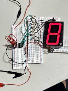
@davee Hi Dave, After some delays, I'm finally back on the counter project. So far, it's good news, I think. The 2003 seems to be a good recommendation, so thanks for that. First off, I want to mention that even though I ordered the 2003AN as per your last advice, what I received is a ULN2003APG.(Toshiba?).
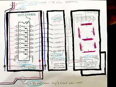
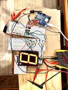
I was going to send them back (pack of 10), but I was excited about getting started, so I forged ahead, which has now yielded some good(?) intel, which I have provided in the photo and schematic below. I am sorry for the crude drawing, but I have no experience with creating diagrams using my computer, like the ones you made, and I just wanted to get this info to you to look at.
As you can see from the drawing, I chose to use batteries to trigger the 7 switches on the IC. I just didn't feel comfortable hooking up the Arduino as of yet. (baby steps). Also, the connections that finally worked for me were slightly different than your drawing. Specifically, the lack of any connection to pin 9. I researched connections that others have used in the past, and what I found mostly were folks that only used pin 9 when they were switching inductive/magnetic loads such as relays, solenoids and motors, to protect the chip from any leftover energy in those devices. Otherwise, pin 9 was unused. So far, all 7 segments have been burning at an acceptable brightness for a couple days on the bench, with nothing getting the slightest bit warm to touch.
I had such trouble with the pinouts for the LED. The wiring on my drawing is completely different from what is shown on the data sheet. Sheesh!
I tried to have my drawing match the photo, complete with the breadboards in bold marker, and the wire colors matching the ones used from board to board. The voltage, resistance and current measurements are circled in light blue, and please know that I'm more than happy to make whatever additional readings if you would like to see more.
Thanks Dave!
Hi Bill @billinfl,
Good to see you have made some progress.
The ULN2003 is one of those 'ubiquitous' chip designs that lots of companies seem to have copied and adapted. If you compare the different data sheets carefully, you will see small differences, such as the maximum voltage they will tolerate, but for applications like yours, where the maximum voltage (12-15V) and currents are modest, I doubt if any of the variations will make any difference.
As you say, the main reason for connection to pin 9 occurs for reactive loads, like relay coils. Personally, I would still connect it to the LED common anode power (+12V line). It may not appear to achieve much, but I think the chip designer would have expected it to be connected, and I can't be 100% sure that the chip designer didn't make any decisions that depend upon it. At worst, connecting it is a small waste of time, as it shouldn't do any harm.
-----------
It looks like your LED current is around 8mA per segment, which should be fine, if the brightness is sufficient. If you need some more brightness, obviously (according to the LED data sheet) you could reduce the value of the 470 Ohm resistors. When you come to wire up the final thing, I would make it so you can swap those resistors, with minimal disruption, as a last minute 'tweaking' job. But, hopefully, you will not need to change them. Lower current should mean less stress, better reliability, etc.
-------------------
The pin numbering on the seven segment displays does seem to be chaotic ... luckily, you seem to have sussed it out. I was more fortunate, the small display digit I had matched your data sheet in this respect!
-----------
You don't seem to have asked any questions, so I am not sure if you were expecting me to say any more at this point.
So for now, I offer my congratulations in getting this far, and hope you can continue to make progress.
If you have any questions, then please feel free to ask them. I offer no guarantees, but I'll do what I can.
I strongly recommend you sketch out the wiring you intend to use, before connecting the HA711 part and the Arduino part. And feel free to post it here, to see if it prompts any useful comments. Whilst I sometimes use CAD systems, this is not a requirement ... pens and pencils are fine, as you have illustrated above.
Good luck, Dave
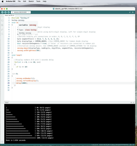
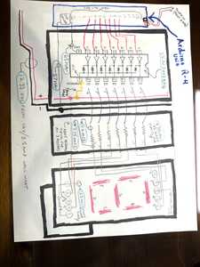
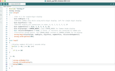
@davee Hi Dave. Thanks for your reply and continued support. I have successfully connected my Arduino Uno r-4 to the 2003 APG chip. (the battery pack is no longer needed). The Uno doesn't seem to have any problem lighting each segment to an acceptable brightness without any parts getting even slightly warm. Please note that I have upgraded the breadboard wiring and the drawing to reflect the proper order of the LED segments from A-G going from top to bottom.(they were random before). I do seem to have a problem, which I have a couple questions about. In an effort to try my first ever experiment with coding, I found a sketch online that would simply count from 0 to 9 in order with a one second interval between each number change. Trouble is, although all digits do light, and change each second, they never make any number, only random nonsense combinations of segments. Can you tell from the sketch I provided what the problem is? I am mindful that the sketch doesn't account for me going through the ic chip, and I'm not sure if that could be the issue. I have tried to troubleshoot this issue, by reversing the order of the pins from the code, but same outcome. Although I'm aware that I could just move on with the project and ignore the random stuff I'm getting, but I feel strongly that if I can't get the display to simply count from 0-10, it spells trouble for more the advanced work that lies ahead. Thanks. Bill
You need to specify the pin that powers the digit when it's being displayed. You've only got one digit but you haven't specified any digit pin in the digitPins array.
Anything seems possible when you don't know what you're talking about.
Hi Bill @billinfl,
Well done for your achievements!
I totally agree, you need to get the basic digits 0-9 working, before moving on.
I notice you have selected a library, which is fine, although it is designed for more complicated cases, including more than 1 digit, so you have a bit more complexity, and something of 'magic' code that it is more difficult to examine.
----------------
BTW You may notice. I provided you with a function that I think did all you needed, i.e. call with a number, and lit the segments, where all of the 'code' was on screen. Essentially, it was an array, which for each digit, it had a 1 if the segment is lit, and a 0 for the segment to be dark. Thus, for different wiring, you just had to swap the 1 and 0s to get the right pattern. I also included a test function to individually identify the segments, as I found it a pain to do. But you have chosen a different path, so let's see if we can make it work.
--------
Anyway, assuming you want to press on with the library, then I would first simplify the test so that it only shows 1 value continuously, and get that digit correct, before moving on. (You can revert it to the 1 second counting test later.)
Note, I am making these instructions up from imagination, which may go wrong ... but let's see if you can figure it out, and report back when/if you get stuck.
----------
Simplify the code inside function loop, to something like.
sevseg.setNumber(8);
sevseg.refreshDisplay();
delay(1000);
Which means it is continuously requesting it to show an '8'.
Hopefully, all 7 segments will be lit, as it doesn't matter if they are swapped over.
If there are less than 7 lit, you need to figure out why. Unfortunately, I don't have the UNO you are using, so it is not easy for me to test.
Don't move on till you get this working, as each next step relies on the prevous ones.
--------------
When you have all 7 segments lighting, with '8' requested, change the 8 to a 1, in the programme and recompile, etc.
With luck, this version will light two segments, but maybe the wrong ones!
You then have a choice of swapping the wires coming into the ULN2003, to choose the right segments, or of swapping the order of the digits in the segmentPins declaration of the programme. Personally, as you have a breadboard, I would swap the wires.
--
When you have a 1 showing on the display, then you should be driving segments B and C, but they might be the wrong way round!
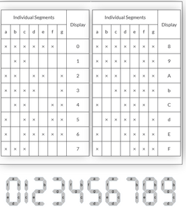
You might find the table below helpful, which is from
https://www.electronics-tutorials.ws/combination/comb_6.html
Note that 1 requires segments B and C to be lit, but 2 lights B but not C.
So change the number requested in the programme to 2, and once again recompile, etc.
From the table, you can see 2 requires 5 segments to be lit, and hopefully you have 5 lit, but probably the wrong 5!!
Initially, just look at segments B and C. If B is lit and C is unlit, then you got B and C correct. But if B is unlit and C is lit, then swap the wires driving B and C.
You should now have B and C correctly wired. Hence, make a note that you should not change these again!!
For now, don't worry that it doesn't look like a '2'. You will need to come back to '2' later, but it is easier to do '7' first, because it only needs on new segment to be correct -- read on...
---------------------
Change the requested number in the program from 2 to 7, and recompile etc.
Consulting the table, 7 requires segments A, B and C. Hopefully, B and C are lit, plus one other segment, but probably not A.
So change the wiring, so that A is also lit, remembering not to change the wiring to B and C.
You should now have 7 on the display, with three segments A, B and C correctly wired.
Add A to the list of segments (B & C) not to change
----------------------
Continue this process, noting it is helpful to look at the table to try to choose a new digit which only has one 'new' segment to find, though this is not always possible. The next digit I would choose would be 4, which unfortunately requires two new segments, F & G, but that is better than some of the others!
Change the wiring (not touching Segments A, B and C), so that it displays a 4.
However, remember F and G may be the wrong way round, so do the same trick hat was used to get segments B & C the right way round. Choose a number that only lights one of F & G. 3 looks like a good choice.
-----------------------
Continue this overall process until you have tested it for all of the digits 0 to 9.
---------------------
When you have got all seven segments wired correctly, revert the program to the form you listed on the screen picture above, and hopefully it will now count through as you would wish!!
--------------
Good luck ... let me know how you get on!!
Best wishes, Dave
Thanks Will, for pointing out another problem ... I was assuming the wiring and the segment declaration order were muddled.
The segment declaration also includes a pin for the not needed or connected, decimal point ... but the hardware driver is only 7-segment. I wasn't sure if the library insisted on this, so I haven't discussed that.
Best wishes, Dave
@will Thanks much Will, for your suggestion. Because I'm a newcomer to making changes to a sketch, (my only experience with changes so far have been to change the delay times between number flashes), I will, embarrassingly, have to hold off on trying your idea for two reasons. One, I'm not sure where exactly (on what line and between which brackets) the digitPins array is. Also, if I haven't specified any digit pins, as you pointed out, I don't get why I'm still getting all seven segments to light, (however wrong their order is). For instance, I have noticed that the first thing that happens when I press the reset button on the Uno is that (I guess as a test for all segments), every segment lights up (showing the number "8"), and then each number is supposed to show up in order from there. I have also noticed that when it gets to "9", the next number is not the "test" above, but rather a zero, with segment "g" dark. So it just keeps running from zero to 9 till you stop it. Lastly, I'm confused that the person who posted the sketch that I'm using, the one I have posted, works for him (or her) without any changes to the sketch.
One last thing: I have noticed, for the first time just before I'm writing this, that the numbers ARE going in sequence, but the segments that are dark are the ones that are supposed to be lit for each number. (Please see the post I'm about to make to Dave for more details.
I appreciate your help, and hope that my apprehension doesn't come off the wrong way.
Thanks again, Bill
@davee Hi Dave, Thanks. Before I scrub in to today's efforts by trying your suggestions, I need to mention that the "random" behavior of the segments is not really that random after all. I am feeling kind of foolish for not noticing this before, as I did spend a couple of hours straight swapping out wires yesterday to try and correct things, (until heroin strength Tylenol was needed,lol), I never noticed what was happening. So, as you may have already read in my response to Wills' post, the LED is in fact displaying the numbers in order, except for the fact that each time a number comes up, the segments that are dark represent the number actually needing to be shown/lit up! Talk about "out of phase"! You will probably not be surprised to hear that not only am I flummoxed as to why this is happening, I'm unclear whether I should be looking at sketch changes, or breadboard changes, (or changes in my choice of hobby) to correct this situation. I didn't want to proceed with anything until I told you about my ah-ha moment. Now, where did I put that white flag? Bill

