Hi all. New member (total microprocessor newb) with questions about feasibility for my first project. Have been enjoying doing basic first experiments with my uno r-4 wifi, and thought of a possible project using a load cell/strain gauge, HX-711 amplifier and a single 3 inch 7 segment LED remote display to indicate how many objects are in a container. (not the weight, just how many).I already have been messing with the load cell/amp with a 16x2 lcd readout and surprised at how accurate it is! There will never be more than 9 objects, and each object will be 6 oz. or so, hence the single LED panel. As a retired maintenance man, I'm able to handle the wiring, soldering, mounting, fabricating etc, but the coding is something that I'm not sure how to proceed with. I did a search on this site for "HX-711", and got pretty scared off pretty quickly at what I saw. (was that in English)? So, obviously I'm in need of help, but I'm new here and don't want to assume anything about how this works, or say/ask the wrong thing. In other words, how do I proceed? Thanks!
Hi all. New member (total microprocessor newb) with questions about feasibility for my first project. Have been enjoying doing basic first experiments with my uno r-4 wifi, and thought of a possible project using a load cell/strain gauge, HX-711 amplifier and a single 3 inch 7 segment LED remote display to indicate how many objects are in a container. (not the weight, just how many).I already have been messing with the load cell/amp with a 16x2 lcd readout and surprised at how accurate it is! There will never be more than 9 objects, and each object will be 6 oz. or so, hence the single LED panel. As a retired maintenance man, I'm able to handle the wiring, soldering, mounting, fabricating etc, but the coding is something that I'm not sure how to proceed with. I did a search on this site for "HX-711", and got pretty scared off pretty quickly at what I saw. (was that in English)? So, obviously I'm in need of help, but I'm new here and don't want to assume anything about how this works, or say/ask the wrong thing. In other words, how do I proceed? Thanks!
Actually this is a pretty easy one. I assume you already have the library installed so just look at the File/Examples/HX711/Kitchen Scales
Now simply modify that code to first of all display on the LCD, maybe a pot to input the weight of one or a button to capture that weight, then simply divide the total weight by the unit weight to give the number.
As it turns out I am also building one to measure out my coffee beans to grind in the morning.
First computer 1959. Retired from my own computer company 2004.
Hardware - Expert in 1401, and 360, fairly knowledge in PC plus numerous MPU's and MCU's
Major Languages - Machine language, 360 Macro Assembler, Intel Assembler, PL/I and PL1, Pascal, Basic, C plus numerous job control and scripting languages.
Sure you can learn to be a programmer, it will take the same amount of time for me to learn to be a Doctor.
@zander Thanks much Ron! Glad to hear you think it's not gonna be a difficult one. I will look into modifications to the code that I'm using now, but I may need some hand holding. Two things; can you recommend a website that best breaks down the (baby) steps to make the changes you suggested? Also, I have purchased both a 3/4 inch and a 3 inch LED readout, but I read somewhere(?) that the larger one (the one I'll eventually need for the project) may need a separate "line driver". (the data sheet says continuous forward current 50 mils, and peak forward current 80 mils). Are you familiar with these? I was thinking of just getting the small one to work, and then switching to the big one when all is working. Sound like a plan? Thanks again.
Like I mentioned, the load sensor driver HX711 has a sample called Kitchen Scale. I am modifying that to NOT use serial input but instead just use 3 buttons for tare, weight (100gms for me) calibrate, and for you the last button weighs and divides by the sample to determine the count.
Also, plan on switching to an Arduino NANO for a finished project, the UNO is too big to package.
Check Bills videos (search his channel on LCD) for some ideas but again the Liquid Crystal library by Arduino provides some samples like Hello World that can be extended to display whatever you need.
Picking a library to read the buttons might be a but of a challenge, I use my own.
As far as display, I would use a 1602. Make sure you get the I2C version, otherwise you will have a lot of wires and pins used. Here is an Amazon link LINK
No idea what a line driver means or those 'forward current'. I really suggest you watch Bills video at
First computer 1959. Retired from my own computer company 2004.
Hardware - Expert in 1401, and 360, fairly knowledge in PC plus numerous MPU's and MCU's
Major Languages - Machine language, 360 Macro Assembler, Intel Assembler, PL/I and PL1, Pascal, Basic, C plus numerous job control and scripting languages.
Sure you can learn to be a programmer, it will take the same amount of time for me to learn to be a Doctor.
Hi @billinfl,
Sounds like you have bought large LEDs that are likely to need a higher current than a microcontroller can drive directly, so you would need an 'amplifier' in each drive wire. The 'amplifier' could be a transistor, or a chip with a group of them. Note, that it often possible to reduce the current by changing the series load resistor, but this might mean the display is not bright enough.
--------
7 segment LEDs can come with a number of different connection styles, so to be more specific it is necessary to see the data sheet or similar.
Switching from the small display to the large display may be a reasonable plan, but there may some changes to the LED software driver, as well as the wiring, depending upon how similar they are, so be prepared.
---------------
Bill (@dronebot-workshop) has published one of his excellent blog + videos about 7-segment displays, which you might find as a useful introduction to some examples of in which the microcontroller drives the LEDs directly, which hopefully will be fine for the smaller LEDs you have.
https://dronebotworkshop.com/led-displays/
-----
If you would like to post links to descriptions of both of the LED types, it might be able to provide a little more information.
Best wishes, Dave
@zander Thanks much Ron! Glad to hear you think it's not gonna be a difficult one. I will look into modifications to the code that I'm using now, but I may need some hand holding. Two things; can you recommend a website that best breaks down the (baby) steps to make the changes you suggested? Also, I have purchased both a 3/4 inch and a 3 inch LED readout, but I read somewhere(?) that the larger one (the one I'll eventually need for the project) may need a separate "line driver". (the data sheet says continuous forward current 50 mils, and peak forward current 80 mils). Are you familiar with these? I was thinking of just getting the small one to work, and then switching to the big one when all is working. Sound like a plan? Thanks again.
Did you actually mean LED, not LCD? If so, I can't help with that as I have never used LEDs for a display. I use either the 2 line 16 char as seen HERE or the big brother of 4 lines by 20 chars seen HERE There are also a few other displays like eInk and various sizes of OLED. For simple displays the 1602 is common, but for a small weather station I am making I use THIS , it is about 2" x 2 1/2"
There are a lot of sizes of OLED displays but more on the small size as they are expensive compared to LCD.
First computer 1959. Retired from my own computer company 2004.
Hardware - Expert in 1401, and 360, fairly knowledge in PC plus numerous MPU's and MCU's
Major Languages - Machine language, 360 Macro Assembler, Intel Assembler, PL/I and PL1, Pascal, Basic, C plus numerous job control and scripting languages.
Sure you can learn to be a programmer, it will take the same amount of time for me to learn to be a Doctor.
@zander Yes, it is an LED that I purchased. It has digit size of 3 inches, because the readout has to be seen from a distance. I'm dealing with the "will the 3 inch one work since it needs a lot of power" issue now. Dave sent me some info for me to check out. Thanks.
@billinfl Ah, did not know you had that requirement. Definitely a job for LED.
First computer 1959. Retired from my own computer company 2004.
Hardware - Expert in 1401, and 360, fairly knowledge in PC plus numerous MPU's and MCU's
Major Languages - Machine language, 360 Macro Assembler, Intel Assembler, PL/I and PL1, Pascal, Basic, C plus numerous job control and scripting languages.
Sure you can learn to be a programmer, it will take the same amount of time for me to learn to be a Doctor.
@billinfl Just a crazy thought from left field, what about one of those strips of programmable RGB leds. They have separate power leads and if it helps you can make the leds do things like pulse or travel etc. You can also choose the colour that is best for the situation. Check out Bill's article at HERE and video HERE
First computer 1959. Retired from my own computer company 2004.
Hardware - Expert in 1401, and 360, fairly knowledge in PC plus numerous MPU's and MCU's
Major Languages - Machine language, 360 Macro Assembler, Intel Assembler, PL/I and PL1, Pascal, Basic, C plus numerous job control and scripting languages.
Sure you can learn to be a programmer, it will take the same amount of time for me to learn to be a Doctor.
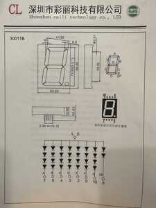
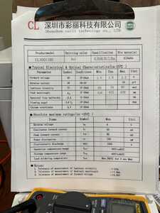
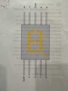
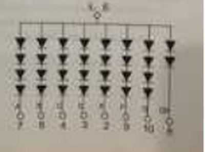
@davee Dave, Here is some info about the 3 inch LED I purchased and I'm hoping to use. I have been doing some reading about "line drivers" (they have other names as well), and it's all above my pay grade. Some use multiple transistor circuits, while others talk about a "matrix"(?). Sheesh, got any Tylenol now. Thanks.
I'll try to drag some images here.
@zander Ron, Thanks for that, but it's really just a simple counter (0-9). I don't have use for letters, colors or anything else. Bummer that my 3 inch high display is just so power hungry! I'm still researching and asking around for help, so I know I'll get there. But hey, if I don't get a solution, I'll just go by something a friend of mine (who wasn't very handy) used to say: "If at first you don't succeed, destroy all evidence of your attempt".
@billinfl Ok, but what I suggested can also do numbers. What you need to determine is the total amperage your display will need. Normally you don't use an UNO pin to drive much of a load, the board you have picked (UNO R4 WiFi) is only capable of 8ma and your LED uses 20ma. What you will need to do is insert a transistor of some sort between the UNO pin and the LED. I will leave Dave (@davee) to sort that out for you as I am an old tube guy with minimal transistor skills. BTW, the NANO can do 20ma but even that is too close, you normally want to leave some headroom but again Dave can comment.
First computer 1959. Retired from my own computer company 2004.
Hardware - Expert in 1401, and 360, fairly knowledge in PC plus numerous MPU's and MCU's
Major Languages - Machine language, 360 Macro Assembler, Intel Assembler, PL/I and PL1, Pascal, Basic, C plus numerous job control and scripting languages.
Sure you can learn to be a programmer, it will take the same amount of time for me to learn to be a Doctor.
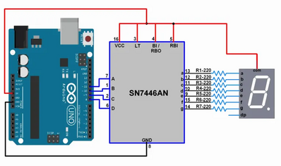
@billinfl, Hi Bill.. was just looking at your post and see that you will require a BCD to 7 segment decoder /driver such as the SN7446AN to interface with your Uno R4, or really any micro-processor.. here's a simple pictorial schematic of a typical connection diagram.
As you can see, there are resistors in the output of the driver to the 7 segment LED..
Hope this helps you with your project....
regards,
LouisR
LouisR
Hi @billinfl,
Sorry .. two minutes after posting, I just saw you only need 1 digit. I've just chopped the surplus stuff.
LouisR's (@inst-tech) suggestion may well work, providing the 7446's are stil available (I just found some in ebay in the UK) and the current limit of 40mA is acceptable.
Apologies to all. Dave
------------------------------
You said you had small LEDS as well .. Depending on their similarity, I might recommend you start with those, and 'upgrade' to the full size ones later.
Can you please post a data sheet for them as well?
-------------
I am a little concerned about the LED data sheet. Pictorially it shows each segment as 4 diodes in series:
But the data sheet says the forward voltage is 2.0V
which is a contradiction, as the drop across 4 diodes in series would be something like 6V to 8V.
We can hope the picture is wrong, but just bear it in mind.
------------------
As I hinted before, the required current depends upon how bright you want it to be.
The data sheet indicates most of the properties at 20mA
so you might think this is a 'suggested' value, but this is the situation where you need to do some testing.
The 50mA is in the Absolute Maximum Values table
This implies exceeding any values in this table will be 'life-threatening' for the device, so you may not want to go this extreme, but say 40mA would be comfortably under the maximum, but would be brighter than 20mA.
-----------------------------------------
Please have a read through, ask any questions that come to mind.
Best wishes, Dave

