15 X = 1.86592 Y = 1.64436 Z = 0.758935
16 X = 1.85222 Y = 1.62825 Z = 0.896704
17 X = 1.86753 Y = 1.6355 Z = 0.796802
18 X = 1.85625 Y = 1.62905 Z = 0.713012
19 X = 1.86108 Y = 1.63469 Z = 0.833056
20 X = 1.85464 Y = 1.62502 Z = 0.88784
I am not sure why there is a tag of "No more attachments are allowed today" with no explanation why.
Hi Chuck
This is because it's your first post, after you make a few more the restriction will be lifted.
In regard to your joystick, are you certain that it is an analog joystick (i.e. two potentiometers) as opposed to a digital one?
😎
Bill
"Never trust a computer you can’t throw out a window." — Steve Wozniak
One other thought - you say that your readings are erratic even when substituting potentiometers for the joystick?
Did you try measuring the voltage being presented to the analog pins as you moved the pots? It should change from zero to 3.3-volts as you move them.
The results you are getting sound to me like the analog inputs are floating, or that you might have a grounding issue.
😎
Bill
"Never trust a computer you can’t throw out a window." — Steve Wozniak
Very strange. I disconnected all the wires from the joystick but the
x = get_voltage(x_axis) and
y = get_voltage(y_axis)
still get varying values
and the other pot is also still registering variable values
13 X = 2.53542 Y = 1.76199 Z = 0.879785
14 X = 0.511596 Y = 0.468896 Z = 0.664673
15 X = 0.4552 Y = 0.474536 Z = 0.617138
16 X = 2.37912 Y = 1.67336 Z = 0.851587
17 X = 1.62261 Y = 1.1521 Z = 0.80083
18 X = 0.086206 Y = 0.219946 Z = 0.596191
19 X = 1.51545 Y = 1.16016 Z = 0.742016
20 X = 2.38557 Y = 1.65886 Z = 0.878979
I will disconnect all of the joystick and the additional pot and start from scratch. The buttons all behave as expected. I think I may have another pico.
If I turn the extra pot all the way counterclockwise, it reads 3.29919 as do the X and Y pins that are not connected to anything now. If it is turned slightly or full clockwise all three get_voltage shows the variable values.
I will do some more experiments later.
- Thanks Bill and DaveE. I have removed all connections except for the ones to the pot -
- power from 3V3 pin 36
- GND to pin 38
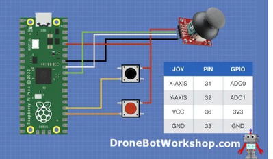
- data connected to ADC0 pin 31
And the data looks good and changes as I turn the pot and is in the range of 0 to 3.29. The second digit to the right of the decimal point wanders around a bit.
Thanks for your help getting me to a known good state.
I will now reconstruct the circuit based on the video and then start adding other stuff.
I have added a reset button connected between GND and RUN/RESET so I do not have to pull out the USB to reset it.
Is there an easy way to identify pins without counting pins on the top of the board? I have a pinout diagram but I still have to count pins.
I have been using Mu (not my favorite editor) because I can see the output on the Serial display.
Another issue: I would prefer to use VSCode but I can't get the CircuitPython extension working again. I stumbled onto getting it working once but I have not been able to get it working again. I think the issue is related to setting up a Workspace which I don't seem to be able to do using the CIRCUITPY drive. It won't accept CIRCUITPY drive as the starting point for a Workspace.
Thanks
Chuck
Hi @chuckuntulis,
Great to hear that you have fixed your initial problem. Getting started always seems difficult. Once you pass the initial hurdles, you can usually move in small steps which are easier to retrace when things stop working.
I don't have an R-Pi Pico, so I am relying on the data sheet, etc. for these comments.
The ADC is specified as 12-bit, i.e. 4096 values, so with a 3.3V ref, it should resolve to ~1 mV.
Fluctuations corresponding to about 1 mV are inevitable. However, 2nd decimal place variations corresponds to roughly 10mV fluctuations, which may be due to noise on the power rail. This may not matter for your application, but perhaps the following suggestions will help if they are an annoyance.
A no-cost option to try is using the ADC-VREF pin 35 instead of the 3.3V on pin 36 to power the potentiometer. This has a simple resistor-capacitor filter, and corresponds to the ADC reference. The absolute ADC values will change by a small amount, but this can usually be allowed for in the software conversion.
Similarly, I would try using pin 33 for ground to the potentiometer, as the data sheet suggests it is intended to be the analogue ground. I also note Bill uses it on his sketch, which is usually a good hint!
As a further measure, the data sheet also suggests adding 3.0V reference like an LM4040, but that may not be necessary .. and obviously requires an extra part.
------
For pin identification, if you have a printer, perhaps you can print some strips to fix next to the board?
-----
Sorry, I have not tried CircuitPython, so perhaps others can help. Maybe start a new thread with a direct question?
Good luck with the rest of your project!

