Hello Everyone,
Let me start by saying I am sorry I really am new at this and I am struggling.
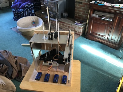
So I have spent the last month trying to build a pinsetter and sweeper for a miniature bowling alley. The goal is that it will pick up the pins sweep the old ones off the alley and then set the remaining pins down again. So I built it, that was the easy part... lol. All 4 servos do what they are suppose to as long as I am controlling them one by one using a HJ Servo Continuity Tester. Now, I would like to code it so that it runs automatically.
So I have an Arduino Uno, and a PCA9685. They are controlling three, 3.5 turn HiTec HS-785hb servos and one 180 degree SG90.
So I started writing the code for this. Where I thought I could just declare the objects the way you would using the Arduino alone... I guess I am wrong because of the PCA9685.
I have commented out some code I am hoping to figure out later for the beam break sensor to that it will help to trigger the necessary action of the pinsetter. However I have to get the running to some degree first. ?
I would love to attach a video as well but not sure if I can here or not... well here is a like to a YouTube video of me controlling it manually with those HJ controllers.
So here is my code... would love to be able to just run it using the microseconds since those are the raw values I already know... maybe that's dumb. Yet getting the servo objects named in order for them to be controlled is priority number one!
Thank you ahead of time to anyone willing to help me!!!
#include <Wire.h>
#include <Adafruit_PWMServoDriver.h>


// Bowling Alley Pinsetter and Sweeper Sequence
// Servos A,B, & C are all 4.5 turn servos Winch Servo HS-785HB
// Servo D is a small 180 degree servo

//Load Adafruit PCA9685 16 channel driver


// IR Breakbeam sensor

// #define LEDPIN 13
// #define SENSORPIN 4

#define MAX_PULSE_WIDTH 2150
#define MID_PULSE_WIDTH 1500
#define MIN_PULSE_WIDTH 800

Adafruit_PWMServoDriver pwm = Adafruit_PWMServoDriver();

// Define Motor Outputs on PCA9685 board

int motorA = 0;
int motorB = 4;
int motorC = 8;
int motorD = 12;

// variables will change:
//int sensorState = 0, lastState=0; // variable for reading the pushbutton status

void setup() {
// put your setup code here, to run once:

// IR Breakbeam sensor
// initialize the LED pin as an output:
//pinMode(LEDPIN, OUTPUT);
// initialize the sensor pin as an input:
//pinMode(SENSORPIN, INPUT);
//digitalWrite(SENSORPIN, HIGH); // turn on the pullup

Serial.begin(9600);

pwm.begin();

pwm.setPWMFreq(60);

}

void loop() {
// put your main code here, to run repeatedly:

motorC.writeMicroseconds(1656);
motorA.writeMicroseconds(1928);
delay(6000);

motorD.writeMicroseconds(1889);
delay(4000);

motorC.writeMicroseconds(1178);
motorA.writeMicroseconds(1474);
delay(6000);

// At this point the program waits until the IR Breakbeam sensor is triggered by the ball.

// Ball Rolls Past Sensor (high) Initiates the next bit of code (if else statement???)
delay(2000);

motorA.writeMicroseconds(1928);
delay(5000);

motorC.writeMicroseconds(1656);
delay(6000);

motorD.writeMicroseconds(800);
delay(4000);

motorC.writeMicroseconds(1178);
delay(6000);

motorB.writeMicroseconds(1160);
delay(7000);

motorB.writeMicroseconds(2033);
delay(7000);

motorC.writeMicroseconds(1656);
delay(6000);

motorD.writeMicroseconds(1889);
delay(4000);

motorC.writeMicroseconds(1178);
delay(6000);

motorA.writeMicroseconds(1474);
delay(6000);

// SPARE SEQUENCE BEGINS

// Ball Rolls Past IR Breakbeam sensor (high) if else statement???
delay(2000);

motorA.writeMicroseconds(1928);
delay(5000);

motorB.writeMicroseconds(1160);
delay(7000);

motorB.writeMicroseconds(2033);
delay(7000);

motorA.writeMicroseconds(1474);
delay(4000);

motorD.writeMicroseconds(800); // Servo D (800us) closes to prepare for bowling pins to be filled

// Needs to loop back in order to restart sequence

// button press to initiate after the setter has been filled/refilled


}
The goal is that it will pick up the pins sweep the old ones off the alley and then set the remaining pins down again. So I built it, that was the easy part...
Nice job on the mechanical side of things Jason! I don't have time to look at your code right now. But I'm sure others will be by shortly to offer you lots of suggestions.
DroneBot Workshop Robotics Engineer
James
Hello @robo-pi,
I am sorry to bother you but it seem is am not getting many replies to my post here... I did find sort of a solution to this post... I created a new post today with 9 views and no comments. I guess I am wondering am I doing something wrong with my posts? I am trying to give s much information as I can so I don't leave anything out.
If you get a quick second to give me posting points maybe??? Sorry
Jason
I wish I could help you out Jason. The code you need appears to be fairly easy actually. Unfortunately I'm facing major difficulties of my own right now. Let me try the following and see if it helps.
Calling all code gurus, @codecage, @frogandtoad, @pugwash, @casey, @ZeFerby, @Spyder, @Pakabol, @triform. Can any of you fellas chime in here and offer Jason some ideas?
Thanks.
Hopefully, someone will be free. They'll all get an email that they have been mentioned in this post.
And my apologies to anyone I didn't list. Please feel free to chime in as well. I just listed the most active posters. If anyone has any ideas for Jason feel free to offer whatever you have.
That's the best I can do for you at this time Jason. Hopefully someone will show up and take a look at your project.
DroneBot Workshop Robotics Engineer
James
I am so sorry to hear that... so thank you for what you have done for me! Means a lot!!!
Jason
Give me a couple of days to look at this board and I'll get back to you!
In the meantime, make a list of all the actions sequentially from the rest position and back to rest!
This needs a real plan!!
I have to go along with what @pugwash has suggested and need to ask for more information.
You have 3 motors that can turn 3.5 times (not familiar with those) and one that turns just 180 degrees.
A, B, & C must be moving the mechanism up and down, and running the sweeper, but it would help to know what exactly is the purpose of each motor. I could maybe envision 2 motors doing that motion but you have 3. To what purpose? And D must actuate the 'pin capture' mechanism. So that is somewhat clearer.
In the motorX.writeMicroseconds(somenumber) method, is 'somenumber' just a value you have calculated/timed to run the motor for that length of time? I'm not familiar with that method so will have to investigate it myself.
It is your design, but I think I would have gone with limit switches to determine the upper and lower limits of the lift mechanism, as well as the forward/reverse travel of the 'sweeper' and not used timed values.
With all of us putting our heads together we should be able to get something running with your pin setter!
SteveG
Yes I was able to watch the video. And thanks for the picture with labels on the 3 motors.
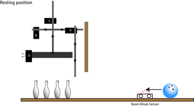
But let's refrain from re-posting videos, pictures, and code multiple times. We are just wasting storage space on the forum server having multiple copies of the same files. I did at least notice this time that your code has comments as to the purpose of the 3,5 turn servos and the 180 degree servo. I missed that the first time. I now see we have lift motors for the pin setter and the sweeper as well as one to drive the sweeper horizontally.
I'm wondering if you have tried experimenting with some test code to get familiar with running the two different types of servos all by themselves instead of trying to jump in and get everything working at once?
I actually have one of the Adafruit PCA9685 driver boards that I received a couple of weeks ago and some 180 degree servos. I haven't had time to experiment with them but maybe, just maybe, can find some time this weekend. I do not have any of the Hitec HS-785HB servos however, but maybe I can make sense of the code sample with the Adafruit library.
SteveG
Ok sounds good... sorry for the reposting of videos...
If I write to milliseconds I am finding it doesn't seem to really matter about the different servos. they both do what I want them too. Really I just need to figure out how to basically three stages out of the loop. I would like the first stage of the loop to be trigger by pressing a momentary switch to set the new set of pins down. Then the next part would wait until the ir beam break sensor would be tripped by a bowling ball so that the next phase of the setter and sweeper would do their thing to set up for the spare frame... then once again it would wait for the ir beam break to get tripped again to then clear the alley and the loop back an then wait for me to put pins back in the setter and press the momentary button to start it all over again.
Sorry very first time in a forum as a active participant... please forgive me!
I am going to attach one more image just as another reference...
Not a problem, you'll get the hang of it pretty quickly. Just remember you can't expect instant answers all the time to your questions. Right now it is nearly dinner time in the eastern time zone of the US (I'm near Atlanta, GA), so I'll be off soon to eat a good meal and may not get back on the forum until in the morning.
I had a pretty good idea of your mechanical setup even without the additional drawing. What would help is a schematic of how you are wiring up the Arduino, PCA9685, and the servos. That will give me and idea of how I should setup something on my bench to look at you code. You could have some wiring issues as well since you say your only control has been with the servo testers.
And you didn't answer the question about where you got the numbers you pass to the write method.
SteveG
... sorry for the reposting of videos...
My assumption was that once you upload an image to the forum you can attach it to as many posts as you like without it taking up any more space?
Just trying to get an overview of your project.
Sequence:
1 Sweeper down.
2 Pin setter down.
3 Grasp pins.
4 Pin setter up.
5 Sweeper moves across and back.
6 Pin setter down.
7 Ungrasp pins.
8 Pin setter up.
9 Sweeper up.
Motor A moves sweeper up/down
Motor B moves sweeper back/forth
Motor C moves pin setter up/down
Motor D locks/unlocks pins
This is the controller connected to the Arduino.
https://learn.adafruit.com/16-channel-pwm-servo-driver?view=all
It can drive 16 servos but you are only driving 4 servos.
This is the library being used.
https://learn.adafruit.com/16-channel-pwm-servo-driver/using-the-adafruit-library
This is the HS-785 Servo Power Gearboxes that retains the position feedback.
https://www.servocity.com/hs-785hb-servo
Do your servos run continuously?
They look like the type of motors ideal for a robotic arm.
If there was a servocity shop nearby I would be down there now to check them out!
Not sure what the command,
pwm.writeMicroseconds(8, 1656);
is actually doing? Does it turn the motor a fixed amount of time?
I understand everyone has a life... sorry... just trying to respond in a timely manner.
I will get you a schematic tonight sometime...
I have gotten those numbers of to the HJ controller itself... here is one example using the code for motorC (the pin setter up and down motion). and it work perfectly actually... Maybe not the ideal method...
#include <Servo.h>

Servo myservoC;

void setup()
{
  myservoC.attach(9);
  myservoC.writeMicroseconds(1655);
  delay(5000);
  myservoC.writeMicroseconds(1178);
  delay(5000);
  myservoC.writeMicroseconds(1655);
}

void loop() {}


