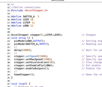
@will Dear Will, Today I have found a couple of pushbuttons and studied your latest and longest sketch carefully. To aid my understanding, I decided to make a complete print-out of such a complex program, but the only satisfactory method I have found ( preserving the line numbers and colours) is screendumping and printing via Photoshop. Is there a quicker way, or do you Arduino experts just study the sketches onscreen?
I am a bit puzzled by your statement that each of the pins connected to the limit switch or the two buttons 'will be declared pinmode(pin INPUT_PULLUP'. When are these declarations made? I can't see any pinmode statements anywhere else in the sketch except one concerning the enable pin.Your sketch was verified perfectly on my computer , so I will try tomorrow to run the code.
Before I connect anything I will send you a coloured diagram as before, with the buttons and limit switch connected without resistors, but I will wait to hear from you about the software setting of the internal pullups before I risk running the program.
I have the text book on Programming Arduino by Simon Monk, but I have not been able to find any reference to DEBUG or the u8 in lines 25-30.
Apologies for my slowness. My only experience of programming was 40 years ago when I used a specialized high-level macro language derived from BASIC to drive the first laser-scanning confocal microscopes: the software for our prototype was written by Richard Durbin, then a PhD student, who later became the chief coordinator of data collection for the Human Genome Project worldwide. My late wife and I wrote a textbook using a BBC Model B computer in the 70s and our first infant used to say 'Mummy, don't do zzzzzz zzzzzz zzz: meaning the dot matrix printer. The BBC distributed free computer programs via ordinary TV sets, after normal broadcasts had finished around midnight..... But I digress...
Brad
@bradscopegems Photoshop is for graphic arts. There are numerous ways to print, I just tried BBEDIT that I know Will uses and it has line numbers and colour. I have written code since the early 60's and have no idea what the various colours mean. They are user configurable and every language, IDE, print program treats them differently. IOOW get used to Black and White, you will be a better programmer if you don't need crutches like colour.
First computer 1959. Retired from my own computer company 2004.
Hardware - Expert in 1401, and 360, fairly knowledge in PC plus numerous MPU's and MCU's
Major Languages - Machine language, 360 Macro Assembler, Intel Assembler, PL/I and PL1, Pascal, Basic, C plus numerous job control and scripting languages.
My personal scorecard is now 1 PC hardware fix (circa 1982), 1 open source fix (at age 82), and 2 zero day bugs in a major OS.
I usually just open the .ino file in a text editor (personally, I use the free version of BBEdit) to print the sketch out. It doesn't colourize the text but I'm used to reading C and C_++ 'raw'. I haven't tried it but you may be able to use the Arduino IDE's copy as Markdown and paste that into an app that handles markdown
I'm sorry, I'm pushing you very hard by introducing commands and concepts that you won't understand. You'll see that at the top of the sketch I use #define to create a value called DEBUG which has the value true. This effectively creates a variable known to the precompiled (the activity that collects all of the code together before the compiler converts it to machine-readable code).
u8 is merely a data type representing an unsigned 8 bit value. There are a lot of different ways of specifying data types in C and C++ (too many, to my liking).
The segments of code wrapped by '#if DEBUG' and '#endif" tell the precompiled whether to include the code in the sketch or not. I'm wrapping print statements that you can use while debugging and testing the sketch. The advantage of the print statements is that you can see what's going on where, the disadvantage is that they use up memory - space that wold otherwise be available to the sketch.
When DEBUG is set to false, all of the code that's in the #if DEBUG ... #endif (except for any #else parts) is no longer included in what's given to the compiler and so all that memory is freed up for your sketch. So, merely by switching the DEBUG value from true to false you can enable a lot of debugging and testing information and reduce the footprint size of the sketch for final operation.
You'll notice two additional files included, SimpleButton.h and SimpleButton.cpp. The .cpp file contains the C++ code required to define a class (library) implementing the operation of a simple button (or switch) and the .h file includes definitions so that the main sketch (the .ino file) can access the functionality of the class.
I did this because I'm lazy. Each button (when properly wired as pin-to-button-GND) is defined by an Arduino PIN number and a debounce time. If you're not familiar with the term buttons debounce, please Google it for a better idea of what it does and how it's handled in the SimpleButton class.
The class creates an independent group of code and data which simulates a button by identifying the pin to which the button is connected and a time (in milliseconds) which is estimated to be needed for the button's physical implementation to gain it's final (stable) state after changing. The class extricates the identical code for the buttons by keeping a single copy of the code and separate storage for the pin and time data, so it represents a real savings in program memory.
Instead of having to write code to handle the creation and testing of each switch, we need only create instances of them (limit, engage, disengage) by specifying a PIN number for each and a debounce time. Then we can use the two methods defined for the class to determine the state of the button/switch. The two methods available are .raw() which immediately returns the state the button (i.e. digitalRead(pin)) and .isON() which returns a boolean value saying whether the button/switch is ON after debouncing is considered.
The class, when created, remembers the pin and debounce time given. It also sets the pinMode inside the class so you don't have to do anything beyond creating the object with the command SimpleButton mySwitch(pin,time).
You don't need to apologize for being slow, it's not a competition 🙂
I hope this cleared up some of what's going on. Keep asking questions about anything that's still unclear.
Anything seems possible when you don't know what you're talking about.
@will Here is what my copy of BBEDIT produced, it's got colour.
First computer 1959. Retired from my own computer company 2004.
Hardware - Expert in 1401, and 360, fairly knowledge in PC plus numerous MPU's and MCU's
Major Languages - Machine language, 360 Macro Assembler, Intel Assembler, PL/I and PL1, Pascal, Basic, C plus numerous job control and scripting languages.
My personal scorecard is now 1 PC hardware fix (circa 1982), 1 open source fix (at age 82), and 2 zero day bugs in a major OS.
I'm too lazy to set the type to C/C++ 🙂
Anything seems possible when you don't know what you're talking about.
@will I don't remember setting that, but maybe. I find the colour a distraction and I haven't printed a listing in many years. With code folding it's easy to focus on whatever code is important on the screen although a portrait screen would be handy, maybe if I ever need to write more than a few dozen lines of code I will get a second screen and mount it in portrait orientation. Or I could try my iPad.
Where is that C/C++ option, I can't find it.
First computer 1959. Retired from my own computer company 2004.
Hardware - Expert in 1401, and 360, fairly knowledge in PC plus numerous MPU's and MCU's
Major Languages - Machine language, 360 Macro Assembler, Intel Assembler, PL/I and PL1, Pascal, Basic, C plus numerous job control and scripting languages.
My personal scorecard is now 1 PC hardware fix (circa 1982), 1 open source fix (at age 82), and 2 zero day bugs in a major OS.
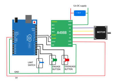
@will Dear Will, I have tried to run your program sketch_jun30a with the buttons. After I have uploaded it and turn on the motor power, the motor locks hard, so it is impossible to turn the leadscrew, but the motor does not turn at all. Neither the limit switch nor the buttons have any effect. I am attaching a diagram showing the connections that I have made. Have I made some mistake? Was I right ( in view of the previous discussion) to remove the wire between pin12 and the ENABLE input of the driver board?
Brad
@will Dear Will, I have tried to run your program sketch_jun30a with the buttons. After I have uploaded it and turn on the motor power, the motor locks hard, so it is impossible to turn the leadscrew, but the motor does not turn at all. Neither the limit switch nor the buttons have any effect.
Hmm, double plus ungood 🙁 I was hoping that @davee had found the only thing wrong 🙂
The motor locking up is probably normal because the driver is responsible to making the motor move somewhere and then stay put. So with power applied and no movement to perform the driver will try to lock the motor in position,
I am attaching a diagram showing the connections that I have made. Have I made some mistake? Was I right ( in view of the previous discussion) to remove the wire between pin12 and the ENABLE input of the driver board?
Your wiring looks spot on.
Leaving off the pin 4 to ENA shouldn't be a problem (that wire was just there so that you could disable the driver which would then let you rotate the shaft by hand).
I'm going to dig through my used parts box, find an A4988 driver and probably a NEMA motor and reproduce your configuration. In the meantime, here's an updated version (jun30b). The only difference is that it has more prints to facilitate tracking what the UNO is doing to look for clues about the failure.
I've also added test for each of the three buttons and switch. You'll get a request on the serial monitor asking you to press each in turn. The sketch will hang until the requested button is pressed.
I'm off to dig out parts now ...
Anything seems possible when you don't know what you're talking about.
I'm going to dig through my used parts box, find an A4988 driver and probably a NEMA motor and reproduce your configuration.
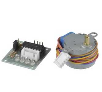
That is the best way to help. If you can reproduce the project you are more likely to solve coding issues quickly. Unfortunately I don't have the A4988 driver or NEMA motor. The only driver and stepper I have used in projects is this little stepper although I guess the principles and even maybe the code might be similar.
Unfortunately the ULN drivers use a different strategy and don't easily simulate the step/dir type drivers.
Anything seems possible when you don't know what you're talking about.
@will Dear Will,
I tried a sanity check, going back to just running the motor back and forth without an limit switch, and all was well. It is getting late here, but I will try to run your new program with the diagnostic messages.
I really am indebted to you: I thought my project was quite basic: I had no idea that it would be so difficult. It is really kind of you to spend so much time on this. But if we can get it going it will save a lot of time for users of the new microscope.
Brad
Don't bother trying the last version, I don't think it'll work either. I'm in the process of trying to set up an equivalent system and trying to get that working. I'll post a working version as soon as I can complete the assembly and test it.
I'm driven now by curiosity, @davee and @zander have pointed out several mistakes and I'm hoping to get a revised edition built and working soon.
Anything seems possible when you don't know what you're talking about.
I really am indebted to you: I thought my project was quite basic: I had no idea that it would be so difficult. It is really kind of you to spend so much time on this. But if we can get it going it will save a lot of time for users of the new microscope.
It's not really that difficult, I just tried to copy and paste some stuff together to cobble a solution; that rarely works. You should always start a project by adding one component at a time and debugging and testing it until it's totally working as expected/desired and THEN proceed to the next bit. I didn't do that before so all of the errors compounded and made the final product even harder to diagnose.
I have now put together a system, piece by piece, that is similar to yours (although not identical) and tested it. It will now home correctly and move reliably from the engaged to disengaged positions. You'll still want to adjust the speed and max speed values as well as the locations of the two final carriage locations.
I have enhanced the testing when DEBUG is set to true. When started it will now prompt for you to press the limit switch and the engage and disengage buttons. It will not proceed until each button has been pressed. This will verify that the buttons are operating properly and also guarantee that there is a limit switch to stop the search for the origin. It also gives you a graceful place to pull the plug if a button doesn't work.
After the buttons are tested, it will spin the stepper forwards and then backwards 1/4 turn to verify that the stepper is operating correctly.
Normal operation is then resumed and it will attempt to roll backwards until it finds and closes the limit switch. You can then use the engage and disengage buttons to shuttle the carriage back and forth along the track. In DEBUG it will print messages back to the serial monitor to help you know what it's doing.
Thanks again to @davee and @zander for suggestions and corrections.
Anything seems possible when you don't know what you're talking about.
Will's latest sketch works! This is wonderful! I feel very grateful to you guys: there is not much I can do in return, as my expertise is all in biology and optics, but if anyone wants a rough drawing (mechanical or circuit) turned into a spiffy coloured diagram like the ones I have been sending to Will, I would be delighted to do it. Not for two weeks though: I must now finish this project and install the viewer in the microscope in the University of Strathclyde ( in Scotland) by 15th July.
I see that I need to learn how to tweak the code. At present, the motor is terribly slow, even at peak speed. The rate is approximately one rev per second, so it takes about 20sec to go from engaged to disengaged and the noise is a bit like a not-very-distant two-stroke engine. I have tried changing 'max speed' from 250 to 1000 but it was only slightly faster. How high can this go? Am I varying the wrong parameter? I know that this motor can go quickly with a quieter and higher pitch hum, but not lose any noticeable torque if it is being driven by a simple code with delays of less than 1000 microseconds between steps. Is the current slowness because of the need to repeatedly poll the switches? Or is that avoided by using clever interrupts?
The other tweak is not urgent, but will be needed to make the program run without the switch tests ( when the Arduino is running unconnected to a computer). Is this done simply by eliminating certain lines in the code? I have just ordered a similar motor from Germany, but , this time, the manufacturer provides a specsheet. I will use the new motor to try to continue my education on steppers and Arduino after delivering the current kit to Strathclyde.
Many thanks!
Good, you're well on your way now.
Here's a link to the class reference for the AccelStepper library. It explains the methods used and the parameters sent to them and should help you with your 'tweaking'. My understanding is that the speed you give the library is steps/second but I can't verify that. You can increase the acceleration value to reduce the time elapsed from speed to max speed (and back).
I don't remember you mentioning any desired speed before, how fast to you need it to shuttle back and forth ?
Again, the main benefit of the library is to provide support for acceleration starting slow and speeding up for the main part of the trip and then slowing down again before stopping.
If you change the DEBUG value to false, then all of the extra testing at the beginning and all printed messages will cease to appear. If you check the sizes of the compiled sketch (DEBUG tru and then false) you'll see the difference in size with the test and print code removed. You should set it false and then try your timing tests again so that you're measuring in its final operational state.
https://www.airspayce.com/mikem/arduino/AccelStepper/classAccelStepper.html
Anything seems possible when you don't know what you're talking about.


