Hi Ron@zander,
There is no reason to combine the 'grounds' because they already are combined at the negative battery post if using battery, or if using wall warts or other DC voltage converters then they are separate with no need to be commended. Clear?
I think I agree with most of your statement, but there is a degree of ambiguity, and you know I am obsessed with getting details right.
I'll try to explain, although it does get a bit abstract, so don't worry too much if its not obvious what I mean.
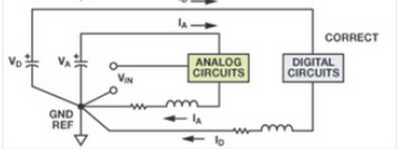
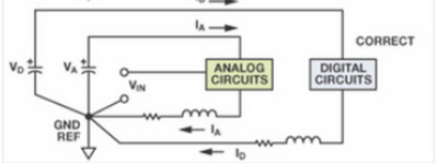
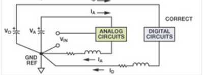
The lower (CORRECT) drawing:
shows two cells .. which might be two wall warts, and one cell is powering ANALOG and the other DIGITAL loads.
Now if ANALOG and DIGITAL had NO relationship with each other, then there would be no need for any common connection at 'GND'. Each cell + load would have a loop circuit, isolated from everything else.
But in reality, the two loads probably 'need to talk' perhaps at the 'data' level, maybe for comms or control.
So they must share a common '0V' base .. so we join the two circuits at a point labelled GND.
This GND is the star point.
And if we add extra supplies and loads, e.g. the Vin is in effect an extra supply, albeit maybe something like a microphone, then this also connects at the same physical star point.
I hope that is clearer.
Best wishes, Dave
(Ps you have probably noticed, but my previous posts have been edited.)
@davee Sorry, it makes no sense. It isn't wrong; it just accomplishes nothing.
First computer 1959. Retired from my own computer company 2004.
Hardware - Expert in 1401, and 360, fairly knowledge in PC plus numerous MPU's and MCU's
Major Languages - Machine language, 360 Macro Assembler, Intel Assembler, PL/I and PL1, Pascal, Basic, C plus numerous job control and scripting languages.
@davee Getting back to the OP's original question.
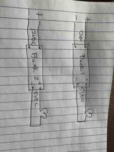
So I was going to connect the ground wires together from the multiple buck converters to all the devices. Any concerns about doing that?
If you change buck converter to a flashlight, what is accomplished by connecting the minus side of the circuit together of 2, 3, or more flashlights. The answer is absolutely nothing.
First computer 1959. Retired from my own computer company 2004.
Hardware - Expert in 1401, and 360, fairly knowledge in PC plus numerous MPU's and MCU's
Major Languages - Machine language, 360 Macro Assembler, Intel Assembler, PL/I and PL1, Pascal, Basic, C plus numerous job control and scripting languages.
I don't understand this diagram. It shows Id departing from GND, running through capacitor Vd, then running clockwise through the wires to the digital section and then clockwise again through a coil, a resistor and back into GND.
This circuit doesn't seem possible, GND to GND.
Also, I don't see ayt 'cells' as in "shows two cells .. which might be two wall warts" ?
Anything seems possible when you don't know what you're talking about.
Will said: don't understand this diagram. It shows Id departing from GND, running through capacitor Vd .. etc.
.... I discuss this further down this reply
Ron Said: Sorry, it makes no sense. It isn't wrong; it just accomplishes nothing.
I Said: Now if ANALOG and DIGITAL had NO relationship with each other, then there would be no need for any common connection at 'GND'. Each cell + load would have a loop circuit, isolated from everything else.
But in reality, the two loads probably 'need to talk' perhaps at the 'data' level, maybe for comms or control.
So they must share a common '0V' base .. so we join the two circuits at a point labelled GND.
Ron, In the literal sense of what the diagram shows, your statement "it just accomplishes nothing." is correct.
Similarly, if ANALOG circuit and DIGITAL circuit are actually each a flashlight bulb, then again, connecting the two circuits together does nothing useful.
-------------------
However, that is because the diagram only shows the main power flow from power source to load wiring.
In a useful computerised system, there is a high probability the two circuits would communicate and/or control each other. The circuit omits this extra detail, to concentrate on the higher current flows, and hence explain the advantage of a star point approach.
I tried to warn about this omission in my description, but sorry I obviously didn't make it clear enough.
--------------------
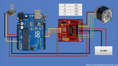
Consider Bill's stepper motor circuit. ... and put the other diagram alongside for comparison
With Bill's diagram, you also have to remember only some of the wiring is shown, albeit in this case a power source is hidden.
The Arduino control + potentiometer on the left are all powered by a 'hidden source', so that the Arduino has 5V supply. The motor has a 12 V supply, on the right of the picture.
Equate the parts of the two diagrams with the diagram I showed
D1 ... Arduino 5V supply <==> VD
D2 ... Arduino and Pot <==> DIGITAL control
A1 ... 12V Power Supply <==> VA
A2 ... Stepper Motor & power driver transistors Stepper Motor chip <==> ANALOG control
So in both diagrams, there are two current loops, each loop having a power source and a power load.
And in both diagrams there is a single point at which the two 'ground' loops are joined
In Bill's diagram, it is at the 'T' in the black wires. In the other diagram, the author has labelled it.
---
Considering the stepper motor example, the two power loops must be joined to enable the input signals from the Arduino connect and 'interact' with the input circuit of the stepper driver chip, causing the driver chip to pass the appropriate higher currents from the 12V supply to the motor. But it is also important to make sure the current loops do not interact in 'unplanned' ways, because this may result in poor or no operation. A 'star' ground approach is one important trick to minimise the chance of 'unplanned' interactions occurring.
I hope this becoming a little clearer.
----------------------------------------------
Will, apologies, my eyesight is obviously worsening with age, but you are right, the author has drawn a symbol which could be taken to mean an electrolytic capacitor rather than cell. However, I think the author is actually drawing an isolated voltage source, which is more of a simulator construct, but a cell/battery with idealised charateristics of the appropriate voltage behaves in the same way.
(Alternatively, you might consider it to be the ouput capacitor of a power supply, where the author has omitted the rest of the power supply circuit which is doing its best to keep the capacitor 'topped up' to maintain a steady voltage output.)
As for current flows, like many (myself included most of the time), the author has obviously used 'Conventional' current, which flows outwards from the positive terminal of the source VD, through the load 'DIGITAL Circuits',
and returns to the negative terminal of VD, via the parasitic inductance and parasistic resistance of the wire, passing through the GND REF point, so that the potential of the circuit at that point matches the potential of the other loop (powered by VA).
---------------------------------
I hope that helps, but this is not an easy area to understand.
Please remember voltage/potential is a 'relative' thing. (Current and charge are 'absolute' things.)
Another 'relative' thing is height.
If you want to measure the height of something, you have define where you are measuring the height from. The height of an airport control tower, from the ground, might be 100 feet, but to an aircraft measuring height with regard to sea level, it might be over 7000 feet high.
Similarly, with voltage. Connecting two or more power loops together at a certain point , like GND REF in the diagram above, is a way of ensuring the two circuits have a common voltage level.
--------------------------
Best wishes, Dave
@davee TLDR: In my opinion, you are performing a huge disservice to newer hobbyists. I had a cursory look at the document you referenced earlier, and it was exactly what I expected of you. This is highly theoretical stuff that the average hobbyist will NEVER encounter.
I do not at all question the accuracy of your data, only its relevance. Yes, there are a few cases where we need to tie together several but not all grounds, and in general, common sense will inform us. Yes, the new folks will not get it at first but will quickly learn what the requirements are and, having learned by doing, will 'get it'.
This thread is already well beyond the length needed to answer the OP, which is a resounding NO. multiple buck converters do NOT need their grounds connected, as is evident in any modern smart home.
I am unsubscribing as this discussion is becoming repetitive.
First computer 1959. Retired from my own computer company 2004.
Hardware - Expert in 1401, and 360, fairly knowledge in PC plus numerous MPU's and MCU's
Major Languages - Machine language, 360 Macro Assembler, Intel Assembler, PL/I and PL1, Pascal, Basic, C plus numerous job control and scripting languages.
Hi Ron @zander,
Sorry. I agree the reference has more detail than required .. but if I quote something from a reference, I think, like (say) Wikipedia, it is courteous to both the author and the reader to credit the source. I didn't suggest anyone should read and digest every word.
Some cases need ground references connected together, some don't care, and others should not be connected. All of these are cases arise in circuits discussed on this forum, albeit they may be simply shown as appropriately connected without comment.
Sorry, but making statements like "multiple buck converters do NOT need their grounds connected", without providing the context, such as the overall circuit, is simply misleading. There is no way of knowing whether they should or should not be connected.
That was the basis of the original question.
----------
I apologise for any mistakes I make, and for when my discussion is irrelevant or unclear, but I do not believe an accurate description of a situation should be swept under the carpet simply because it is hard to understand. We all often oversimplify a situation for convenience, but this should only happen if that simplification is justified.
Newton's concepts of motion work well at the speed our cars move, but fail when considering objects approaching the speed of light. This simplification is easy to justify.
Electrical/electronic circuits live in more of a twilight regarding justification. The simple circuit principles are usually enough for flashlights and mains wiring, but some of our electronic boards of just $1 or two, are pushing into areas that are far beyond the simple rules. And these rules are those of physics, not human decided laws. Of course, much of the time, we may still 'get away with' breaking the rules, but that does not mean we have a free pass to ignoring all of them, all of the time.
---------------
So, if I am unwelcome, then I will go away, but if I am here, I will politely try to be full and accurate in my answers. I apologise for my weaknesses but not for trying to be truthful, including the 'whole truth'.
Best wishes and take care, Dave
@davee Indeed, you are correct ,and succinct as usual.. The problems with breaking the rules of proper grounding, or ignoring them, can be quite catastrophic. While hobbyist may or may not encounter the havoc of improper grounding that can occur, I can assure you that in industrial and commercial electrical and electronics, improper grounding can create all sorts of problems..such as ground loops, induced EMF and EMI on control wires because the shield wires were cut, or not earth grounded. Even if you're a newbee.. the purpose of your hobby is to learn as much about it as you can so as to facilitate being able to expand your project scope of what is possible to build , or tinker with. I for one, enjoy your "sermons".. 😀 and do believe that they serve the purpose of edification to those that merely read our post, but don't necessarily interact with post of their own, which I perceive are the vast majority of the forum. Keep up the fine work, as the rest of us are still eager to learn!
Although I spent 49 years in electronics and industrial electrical instrumentation, I too still try to learn something new every day, and your post, if nothing else, always brings me back to things that I have forgotten or possibly never fully understood..
Kind Regards,
LouisR
LouisR
@inst-tech NONSENSE. In this case the multiple buck converters are driving separate loads.
First computer 1959. Retired from my own computer company 2004.
Hardware - Expert in 1401, and 360, fairly knowledge in PC plus numerous MPU's and MCU's
Major Languages - Machine language, 360 Macro Assembler, Intel Assembler, PL/I and PL1, Pascal, Basic, C plus numerous job control and scripting languages.
@inst-tech @davee Just a reminder: this is a slightly simplified version of the OP's original question. I am VERY familiar with it as I installed more than this in my RV: pantry lighting controlled by a mag switch, under-island lighting controlled by a mag switch, island edge lighting controlled by a radar sensor, main water valve controlled by multiple switches, and Alexa.
First computer 1959. Retired from my own computer company 2004.
Hardware - Expert in 1401, and 360, fairly knowledge in PC plus numerous MPU's and MCU's
Major Languages - Machine language, 360 Macro Assembler, Intel Assembler, PL/I and PL1, Pascal, Basic, C plus numerous job control and scripting languages.
Hi Ron @zander,
That is your pair of independent circuits each using a buck converter, and a dedicated load, one wouldn't expect to need a common connection.
But that is not the only circuit that has ever used two buck converters.
I emphasised that some cases need a common ground, some should not have a common ground, and some don't care. Identifying the correct case, (unless it happens to, by chance, to be a don't care,) is vital.
e.g. a single video card in a pc may have 8 or more buck converters on small board, each driving separate loads, and probably twice that number in the whole machine. Most, probably all, of these converters, will need careful connections to a common 'ground' for a reliable machine.
As the questioner didn't provide a circuit, I had, and still have, absolutely no vision as to whether they were all isolated or not.
I tried to provide a glimpse into the issues involved.
Best wishes and take care all, Dave
I tried to provide a glimpse into the issues involved.
And I'm very glad you did too. 👍 I sort of understood the idea of a common ground but had no idea of the desirability of choosing the correct point at which to do it. Keep the good 'sermons' coming.
PS I also see the OP did not specify the circuits would not interact as he who pretended to unsubscribe from these posting keeps carping on about. 🙄
@davee HE SAID IT'S A CAMPER. There are only 2 simplifications in my drawing: the loads will be different, and if there are any interconnects, he will use level converters.
I was sure of the result, but just for chuckles, I pulled out a buck converter and metered the input -ve and output -ve. They ARE connected, and since the inputs to the bucks go to the battery bank, ALL the -ve are connected. So, to answer his question of
So I was going to connect the ground wires together from the multiple buck converters to all the devices. Any concerns about doing that?
None at all; they are already connected, so you do NOT need to.
It also will not hurt to make even more connections. (just to keep Dave happy)
First computer 1959. Retired from my own computer company 2004.
Hardware - Expert in 1401, and 360, fairly knowledge in PC plus numerous MPU's and MCU's
Major Languages - Machine language, 360 Macro Assembler, Intel Assembler, PL/I and PL1, Pascal, Basic, C plus numerous job control and scripting languages.
@davee @dronebot-workshop The problem is the OP asked a simple question, and you went off on a sermon. I was hoping you would learn something, but I was being foolish. I am sure everything you said is true (except for that one diagram you copied; it was a horror story), but could you try to match your answer to the question in the future?
MAYBE we need a new sub-forum. We should call it Dave's Corner or something similar. I am serious, Bill, can you consider this?
First computer 1959. Retired from my own computer company 2004.
Hardware - Expert in 1401, and 360, fairly knowledge in PC plus numerous MPU's and MCU's
Major Languages - Machine language, 360 Macro Assembler, Intel Assembler, PL/I and PL1, Pascal, Basic, C plus numerous job control and scripting languages.
A simple request, a good and thorough answer, and many many many more posts from the topic unsubscriber ranting on about something. I think a special sub forum called Rons Rantings is called for. BTW it is quite possible for two circuits in a camper van to be connected for comms thus the desirability for a considered grounding scheme to be warranted. Simple answers can be very misleading.

