Hi,
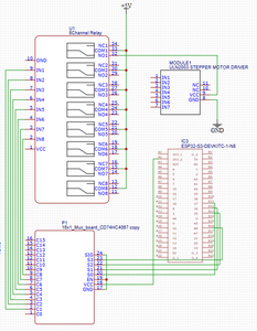
I have a project I am working on that drives 8 28byj-48 stepper motors, one at a time. All 8 control boards share the same 4 io pins on the ESP32. I currently control the power to the steppers through a multiplexer board, its output turns on one relay on a 5v 8 relay board. This all works fine.
I would like to move this to a custom PCB.
I would like to eliminate the relay board to both reduce the number of connection wires and the footprint of the relay board.
In researching it seems that I could use BSS138 MOSFETS in place of the relays. Any advice on what additional components I should use to protect the ESP32 or MOSFETS?
Thanks,
Bill
Hi @billo4th Bill,
You should be able to replace the relays with solid state parts.
You ask about protection, which means analysing the circuit you intend to build. You may not need anything 'special', as the motors are only low power, but without a circuit diagram it is difficult to even imagine what issues are likely to appear. If you posted a sketch of the circuit, you might get some useful feedback.
I presume you will be making sure the power supply lines have adequate decoupling, and consider the physical paths, trying to make sure the lines carrying motor power are kept away from those associated with microcontroller power and the data lines.
You may note that Bill (@dronebot-workshop) says in the text at
https://dronebotworkshop.com/stepper-motors-with-arduino/
about driving the same stepper motor:
On the subject of power supplies one very important thing to note is that you should NEVER use the 5-volt power from your Arduino to power this (or any) stepper motor no matter how tempting it is. Even though the 28BYJ-48 doesn’t draw much current it will induce electrical “noise” onto its power supply lines and this could damage your Arduino. Always use a separate power supply to power your stepper motors!
============
You mentioned a transistor part number, so I looked up the data sheet.
Looking at the MSS138 MOSFET data sheet: https://docs.rs-online.com/1ff3/0900766b80d22ec5.pdf
(click image to enlarge)
this device is intended for circuits that have 5V to 10V available for driving the gate.
(Do not get confused by the looking at the Vgs(th) value, which is about the "worst case leakage current" when it is being switched off.)
The ESP32 is a 3.3V device, so drive voltages will typically be in the 3V to 3.3V range, which isn't enough to guarantee a low drain-source resistance when it is being driven 'on'.
(I am not saying the device cannot work, because this depends upon the circuit is expecting it to do, but rather this device is designed for a different situation, and not well suited to this one.)
-------
Choose MOSFETs where a low "Rds on" is specified with gate voltages of near 2.5 V, when the gate is being driven by 3.3V logic parts.
The data sheets of such devices sometimes use phrases like "logic gate compatible", which is a useful hint, but don't rely on it or ignore a device which doesn't mention it, check the numbers.
------------------------
You should be able to find some MOSFETs in a similar package, etc. to act as drop-in replacements.
Best wishes with your project, Dave
Hi Bill @billo4th,
Thanks for the sketch ... that helps a lot in clarifying what you are doing.
I am pretty sure I understand your circuit, but just to be safe, I'll go through it.
---------------
My interpretation of your sketch (please tell me if I have it wrong), is the ESP32 puts out a 4 bit code onto S0..S3, which selects a particular path inside the 4067.
e.g. just considering inside the 4067
with S0 = 0 S1= 1 S2=0 S3=0, then SIG connects C2 with an internal resistance of (say) 100 Ohms
C0, C1, C3,C4... C15 are all 'isolated' from SIG, and (everything else)
Since SIG is connected to 0V/GND, then C2 will have a low resistance path to ground.
I assume each of the relay inputs IN1 to IN8 has a pullup resistor to VCC, of say 10kOhms
So C2 will pull IN2 voltage to near 0V, while the other INs will all be 5V
Pulling IN2 to near 0V, will activate relay 2, and COM2 will connect to NO2, and hence NO2 will supply 5V to power Module 2, and hence to the associated ULN2003 and motor.
-----------------
I think we can replace the relay board with just one resistor and one p-channel MOSFET per relay replacement.
Note p-channel, not n-channel which the device you suggested was.
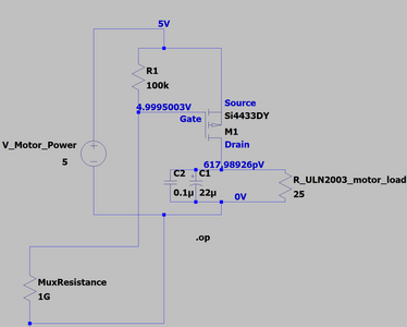
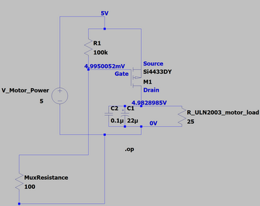
As a circuit sketch + simulation, I have two pictures to discuss:
Motor Not selected and powered off
Motor Selected and powered on
The 'circuit' consists of two main components M1 and R1, which are required for each channel.
The other two resistors are simulation only parts to represent the rest of your system, and have names to describe their 'function'.
MuxResistance is the particular path resistance inside the 4067 chip, from the Cx pin to the Sig Pin.
In the 1st picture, it is assumed that the ESP32 had selected one of the other paths, so that resistance of this one was very high ... maybe 1GigaOhm.
In the 2nd picture, it is assumed that the ESP32 had selected this path, so that resistance of this one was low ... maybe 100 Ohm.
R_ULN2003_motor_load is a 25 Ohm resistor, representing a rough guess of the effective resistance through the chip and motor windings when both windings are powered.
I also added a couple of capacitors as a 'reminder' of what you might like to add to the power supply path to each ULN2003, in the hope of reducing the switching noise propagating too far afield. The values are just first guesses - estimating such things is notoriously difficult. If your existing setup works, then I hope the new one will also be fine.
------
Thus, in the 1st picture, R1 is able to pull the voltage on the gate of the MOSFET to almost 5V (with respect to GND/0V), but in the second picture, the gate voltage will be almost zero, because of the 100 Ohm path to GND through the 4067.
These gate voltages will be reflected in the path resistance of the MOSFET, from source to drain: In the first picture it may be more than 1GigaOhm, whilst in the second picture perhaps 0.2 Ohm.
The simulator has superimposed the voltages it calculated for each case.
----------
The MOSFET number was chosen from the list that come with the simulator, but it doesn't mean it is a practical part.
You will probably have discovered, the list of parts to choose from is enormous.
----------------------
Being a skinflint, some time ago, I went to AliExpress and ordered some parts I thought might be useful, principally on the basis of them being available in a substantial quantity for a couple of pounds/US $.
On this basis I have a strip of about 100 devices, which were claimed to be Si2301, probably labelled A1SHB, which I think is roughly similar to the simulated part. A quick check suggested maybe similar parts are available from Amazon UK, albeit at about 3 x the cost, but with quicker delivery.
Obviously, such purchases are something of a gamble, but so far my luck has held. If I was looking for a 'professional' result, then I would look to somewhere like Farnell, but if it is just for my personal amusement, it seems fine.
This data sheet will give you some idea of what they claim to be like.
https://www.vishay.com/docs/72066/si2301bds.pdf
I'll leave you to decide. I am sharing my limited experience, not making a recommendation. All responsibility of outcomes is yours.
-----------------
I would however recommend you prototype the hardware, before committing to a PCB design. Unexpected bugs have a habit of trying to hide.
Hope this helps, and good luck with your project.
Best wishes, Dave
Hi Dave @davee,
Thank you for the circuits, they look great. Like you mentioned, I'm trying to do this on the cheap. I would like to build several units when I'm done, so I was looking for quantities greater that eight. Just thought I'd run my selections by you before actually purchasing. The cost is not so much if the choices don't work out.
aliexpress.us - 100nf capacitors.
aliexpress.us - Tantalum Capacitor 16V22UF
Thanks,
Bill
@billo4th Do you understand those are extremely tiny surface mount devices? You will most likely need an air gun and solder paste or an oven (could be home made) I didn't notice a size spec, but at least some of them are the smallest (smaller than a grain of rice) so a soldering iron will not work.
First computer 1959. Retired from my own computer company 2004.
Hardware - Expert in 1401, and 360, fairly knowledge in PC plus numerous MPU's and MCU's
Major Languages - Machine language, 360 Macro Assembler, Intel Assembler, PL/I and PL1, Pascal, Basic, C plus numerous job control and scripting languages.
Sure you can learn to be a programmer, it will take the same amount of time for me to learn to be a Doctor.
Hi @billo4th,
I hope it all works!
As I said, I strongly recommend prototyping the circuit, before ordering PCB design.
In which case, if you don't already have any, get a few adapters for the FETS ..
e.g. https://www.aliexpress.us/item/33016727218.html
I would probably have chosen 1206 size 0.1microF capacitors for my clumsy hands, but 0805 are not too bad.
And also I have corresponding adapters, for prototyping with the capacitors.
Don't forget the 'R1' pull-up resistors.
Good luck, Dave
Hi Dave @davee ,
I will most definitely be prototyping the circuit on a breadboard before considering the pcb design. I took your suggestion and switched the .1microF to 1206, and the tantalum to C 16V22UF. I also have the R1 resistors in my cart, also 1206's. I just didn't add the link.
Thanks again, and I will follow up once I get the parts and test the circuit.
Bill
Hi @davee ,
I finally received my components from Aliexpress. The SI2301 mosfet works perfectly. I'm not sure how to interpret the datasheet for them, but they also work to switch the 3.3v power to my touchscreen LCD backlight. My device will be powered 24x7 but the display is only needed a few minutes a day. I was using a PN2907 for that, but now I can change it to a smd.
Thank you again for your circuit example and feedback. I feel ready to start on the PCB design.
Regards,
Bill
Hi Bill @billo4th,
Thanks for your kind reply. Good to hear you are making progress. Ordering from AliExpress does require a degree of patience. In a very modest way, I have tried to buy some components to make a store of 'cheap' bits like resistors, small transistors and so on, so that I can throw a few parts together, without waiting. Of course, there will always be missing parts, but it's a start.
If you are not familiar with MOSFETs, then they are rather different from their bipolar cousins. They are worth looking up. Also, I suggest using a simulator to find out how a typical device behaves, although I appreciate that is a new learning curve for many. I tend to use LTSPICE, which is free download from Analog Devices, but there are several alternatives which are also free.
Start with a part or parts you understand, even just a voltage source and a resistor. Build up some experience, then move to the parts that are less familiar. You may not find the model for an exact transistor number, but just look for one that looks fairly similar.
Of course, if there is a particular line or two on the data sheet that is confusing, etc. you can always try asking here.
Good luck with your PCB and your project as a whole. Please keep us informed of progress.
Best wishes, Dave


