Hi @horst,
I suspect you haven't 'met' a stepper motor driven by Arduino, and if that is the case I suggest you start with some simple experiments, probably using the descriptions provided by Bill (@dronebot-workshop) and maybe others as well, to get 'comfortable' with them, as they are rather different from the motors most of us have used, such as in model trains and cars, electric drills and mixers, etc.
With the stepper motor, if the current is simply applied to the windings, it may move a degree or two, but then it will just stay in that position. It will also resist attempts to rotate it manually. The torque that it can exert is proportional to the current through the motor.
To make the motor move, it is necessary to switch the currents going through the windings, with a switching operation for each step. Thus, the driver, assisted by a controller, e.g. Arduino, is required to cause the motor to rotate the motor.
Although the current through the motor will be affected by the applied voltage, the relationship between current and voltage, when it is moving, is not the simple Ohm's law relationship that applies when a voltage is applied to a resistor. Hence, it is common to provide a moderately high voltage, e.g. 24V to the driver electronics, and rely on the driver to constrain the current, and hence the torque, that the motor is producing.
In most applications, such as moving the arm on a robot, the current will be set to a convenient value which ensures the arm will never be 'stalled' by any expected load. This is likely to mean, any attempts to manually force it to a different position will fail, as the motor will be able to exert enough force to 'win'.
In this application, I suggest a more subtle adjustment may be required, such that the motor will always overcome gravity, friction, etc., but can be readily overridden by the pilot manually applying a force to the wheel. It will then be necessary for the sensor (say a pot) to determine the difference between the 'auto' commanded position and the manually constrained 'actual' position, and to change the commanded position accordingly. (Sorry, I can only imagine possible scenarios, as I have never flown a plane.)
Hence, I recommend you try building some simple experiments to ensure you can achieve the required 'look and feel', before committing to a final design. If I was doing it, I would expect to need several iterations before I even got close.😐 😐
Best wishes, Dave
Hi Ron @zander,
I agree with your descriptions about commercial aircraft, and as modern military jets are reputed to be so 'unstable' that they are (almost?) unflyable by humans alone, I assume they too allow the flight control systems to override the pilot's commands. Similarly, I was aware that Boeing had moved to fly-by-wire with 'newer' models, but I assume its yoke system, to some extent, imitates the 'feel' of the previous direct controls.
As I am not a pilot, I am not clear how the auto-pilot and human pilot may interact, plus I find it hard to imagine the exact form of the controls. I can easily imagine the extremes, in which one or other is in full control, but can the human directly overrule the auto-pilot in an emergency, simply by forcing the control, without first switching the auto-pilot off?
Personally, I suspect stepper motors are fundamentally better suited to a simulator, as they allow very precise position and torque control by electronics plus software, but as I have consistently pointed out, the standard common driver electronics may need some modification, which many amateurs may find difficult to provide.
Maybe commercial servos could be applied more readily, but I do not have the experience to suggest any suitable products, etc. And part of the choices will be related to the wish to keep to the methods used by the authentic cockpit equipment.
Best wishes, Dave
@davee Yes, auto pilot turns off the moment the pilot touches any control that is part of that system. You mentio servo, and so did the OP, that may be a viable choice as well.
I think the OP is very well versed in the subject matter, and we have told him that the stepper should be either powered off or some protection circuits employed.
I have not flown a modern unstable jet, my reflexes are waaaaaay too slow. I have flown a Colt canvas bodied trainer, Cessna 130 and my favourite a Cherokee Piper 150.
First computer 1959. Retired from my own computer company 2004.
Hardware - Expert in 1401, and 360, fairly knowledge in PC plus numerous MPU's and MCU's
Major Languages - Machine language, 360 Macro Assembler, Intel Assembler, PL/I and PL1, Pascal, Basic, C plus numerous job control and scripting languages.
My personal scorecard is now 1 PC hardware fix (circa 1982), 1 open source fix (at age 82), and 2 zero day bugs in a major OS.
Hi Ron,
Thanks for the update.
Out of curiosity, you say "Yes, auto pilot turns off the moment the pilot touches any control that is part of that system".
If the control is something like a wheel (or lever), does that mean the pilot can physically rotate the wheel by a small amount, etc, and that will automatically be sensed and converted to an 'autopilot off' command, as well as applying the rotation command to the aircraft flight surfaces, etc., or that there a hidden "switch" when the pilot grips the wheel (or similar), which first disables the auto-pilot, and hence subsequently, allows the pilot to rotate the wheel?
Best wishes, Dave
@davee Nothing hidden, just moving any control surface does it. Here is what the OP said.
If the autopilot is flying the plane (and adjusting the trim) and the pilot engages the rocker switch (or manually moves the wheel), the autopilot is automatically disengaged.
First computer 1959. Retired from my own computer company 2004.
Hardware - Expert in 1401, and 360, fairly knowledge in PC plus numerous MPU's and MCU's
Major Languages - Machine language, 360 Macro Assembler, Intel Assembler, PL/I and PL1, Pascal, Basic, C plus numerous job control and scripting languages.
My personal scorecard is now 1 PC hardware fix (circa 1982), 1 open source fix (at age 82), and 2 zero day bugs in a major OS.
Hi Ron @zander,
Thanks for that clarification ... that implies (to me) that the " pilot engages the rocker switch", to allow the pilot to take control, would be a trivial task to implement, but the "or manually moves the wheel", will be a more subtle and challenging system to construct, assuming that the auto-pilot (or other auto-xxx), mechanically moves the same wheel, whilst it is in control, since it implies the pilot is physically 'stronger' than the auto-pilot control, and the aircraft system is detecting the difference in actual position of the wheel, compared to the value the auto-pilot has requested.
By carefully controlling the current drive to a stepper motor, it should be possible for the motor to reliably drive the wheel, whilst still allowing the pilot to override the motor.
Best wishes, Dave
@davee Since I only flew smaller airplanes, I don't know how the big boys worked, but in any case, the switch on the yoke is right there. I think in the Piper Cherokee 150 I used a switch on the wheel.
One thing to keep in mind, the OP isn't trying to copy the real machine, he just wants a big flight sim that is operated as close to the real thing as possible. If you go back and red his posts you will see what I mean.
First computer 1959. Retired from my own computer company 2004.
Hardware - Expert in 1401, and 360, fairly knowledge in PC plus numerous MPU's and MCU's
Major Languages - Machine language, 360 Macro Assembler, Intel Assembler, PL/I and PL1, Pascal, Basic, C plus numerous job control and scripting languages.
My personal scorecard is now 1 PC hardware fix (circa 1982), 1 open source fix (at age 82), and 2 zero day bugs in a major OS.
Hi Ron,
I am actually trying to "imitate" the real airplane electric trim behaviour as close as possible, which I think I can achieve with the stepper. The way I described it in the previous post is exactly how the King Air 200 elevator trim behaves. You can manually adjust, you can adjust with a rocker switch on the flight yoke and the autopilot also can adjust it. All this can be achieved through the flight simulator software and Arduino. I have done it in the past (with a gearbox attached to a DC motor).
The only reason I am not using a DC motor again is because of the special mechanical construction of this elevator trim, which doesn't allow me to use gears because of space and because they are hard to move manually. The stepper has a better "feel" to it in that sense.
The reason for the OP was not to understand how the elevator trim works in a real airplane (GA or General Aviation), but to ask for opinions regarding rotating the shaft of the stepper motor when it is NOT active/energized and if the resulting induced current could affect the motor driver.
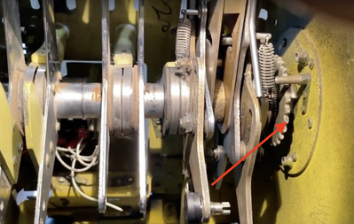
I am very appreciative of all the comments and inputs. I have attached a picture or the throttle quadrant for the King Air 200, which I am rebuilding. You can see the big elevator trim wheel, as well as the sprocket on the inside of the throttle quadrant.
Thanks for all the help guys.
Horst
Hi Ron,
I might well have completely mistaken the OPs intentions, and if so, I apologise for any confusion, etc.
My thoughts have been influenced by a few pictures and articles I have come across, of people buying parts from aircraft scrap merchants and spares sales outlets, to construct cockpits which are as 'authentic' to the original design as possible. I have never met anyone who has done this, but I assume they aim to produce an 'environment' that would 'almost' convince a pilot familiar with that aircraft that they were sitting in a real aircraft cockpit, and the controls are connected to real aircraft systems.
Inevitably, 'authentic' will be a somewhat 'artistic' measure, as few will have the space and resources to procure an entire 737 to house and 'animate' their 737 cockpit, implying they will have to make decisions about which parts, mechanisms, etc. will be entirely 'original' and which will be emulated.
Hence, I do not pretend to know what decisions any particular constructor would make, and I think the descriptions I can read in a forum post or two are always going to be inadequate for me to fully visualise the intentions, but I suspect there will be more alternate views as to how it should be done, than active constructors. So, whilst I may offer suggestions as to how a particular effect might be implemented, I'll leave the decisions as to what is 'best' or 'most authentic' to others.
Whatever they decide, I wish them luck and success.
Best wishes, Dave
@davee Thank you. The goal of this training device (and others that I have built) is for professional use at a small airline. They are not to teach people how to fly (you can only do that in a real airplane), but to be used as a procedural trainer. What this means is that the company has very specific procedures for different scenarios and they want to make sure all their pilots use those same procedures.
The importance of using real airplanes is that the pilot will find the same set of switches, levers, knobs, etc as in the real airplane so that when he/she steps into the real King Air 200 from that company, everything will be where it is supposed to be. Flying commercially nowadays is more about following procedures than actually flying, or so it seems 🙂
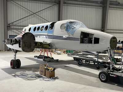
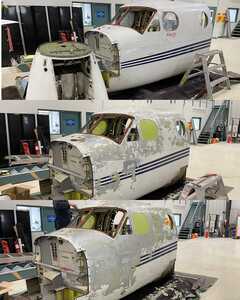
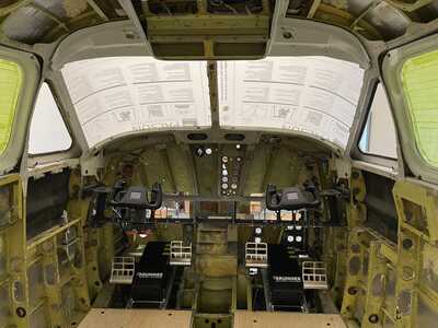
I have attache a few additional pics of the project, which I started a few months ago.
Cheers,
Horst
How it started
After cutting the cockpit
The inside of the cockpit as I am building it
Horst
Hi @horst,
Thanks for the extra detail.
--------------
A niggling thought in the back of my mind concerns your description "At the back of the stepper, a potentiometer (with 10 rotations) is attached to the shaft of the stepper so I can measure the rotation/angle of the main trim wheel."
Using a potentiometer in this way is perfectly sensible, providing it provides sufficient precision and accuracy. You may be considering a component which is carefully constructed and specified, for such a purpose. However, if you are considering a 'general purpose' device, which would more commonly be fitted to the front panel of something like a variable voltage power supply, I wondered if it would be sufficiently linear, free from backlash, and provide the required resolution for your purpose. As a 'front-panel' control, some loss of linearity would often be automatically be compensated by the user adjusting the control, but when being used as a precision angle sensor, it becomes a measurement error, that might be a problem, especially if the auto-pilot commanded the wheel to go to a certain angle, but the sensor indicated it was at a different angle. The system would need to decide if the difference was due to a system error, or the pilot moving it to this alternate position.
Please note, I am not saying this will be an issue ... just raising it as a point you may wish to check during early prototyping, before committing to a final design. It is feasible that you will need to build hysteresis into the sensing chains, possibly to avoid problems with vibration, etc, that will also hide any deficiencies of the potentiometer.
However, if you find a potentiometer is not good enough, then many rotation sensors using either optical or magnetic methods are available, which claim resolutions down to small fractions of a degree, but their usage would be a whole new discussion.
Best wishes and good luck, Dave
First computer 1959. Retired from my own computer company 2004.
Hardware - Expert in 1401, and 360, fairly knowledge in PC plus numerous MPU's and MCU's
Major Languages - Machine language, 360 Macro Assembler, Intel Assembler, PL/I and PL1, Pascal, Basic, C plus numerous job control and scripting languages.
My personal scorecard is now 1 PC hardware fix (circa 1982), 1 open source fix (at age 82), and 2 zero day bugs in a major OS.
Thank you guys, yes, the accuracy of pots is something I have been battling since I started building these simulators. And as you say, it depends on the application. For things like throttle levers and trims, they are used in almost all "brand named" simulators I have looked at, provided that the percentage of accuracy stays within limits (1% - 5%). In real life and in the world of general aviation (GA) where fly-by-wire is not as common, the margin of error is wider than with fly-by-wire planes.
Reciprocating engines, as well as controls based on levers, pulleys and cables are not that precise in real life either. Having said that, a lot can be "manipulated" via the code on the Arduino, but I try to use only high quality components that will stay within an acceptable range, not only for accuracy, but also durability as these machines get used a lot.
On a side note, I have used Hall effect angular sensors for instruments and gauges as those require high precision, i.e. a compass knob. I get 0.01 angular accuracy for those.
My intention is to use magnet (5mm cylindrical) at the opposite end of the shaft of the stepper that is coupled (via a 3D printed ring) to the potentiometer. This way, if for whatever reason the trim wheel is rotated too far and the pot hits its physical limit, the magnet will let go of the pot shaft and not destroy it.
Horst
@horst This is what you may need, not sure if you knew about these. Belt driven through a magnetic clutch should work, but also counting steps on the stepper is the first line of defence. FYI, if it can slip, it is measuring relative angle, not absolute. Change .ca to your country.
First computer 1959. Retired from my own computer company 2004.
Hardware - Expert in 1401, and 360, fairly knowledge in PC plus numerous MPU's and MCU's
Major Languages - Machine language, 360 Macro Assembler, Intel Assembler, PL/I and PL1, Pascal, Basic, C plus numerous job control and scripting languages.
My personal scorecard is now 1 PC hardware fix (circa 1982), 1 open source fix (at age 82), and 2 zero day bugs in a major OS.
Just for your info (thanks to everyone for contributing), I was able to make the stepper work in a way that is suitable for the simulator. The driver has a pin called "Enable", which energizes (or not) the motor. When setting this pin to 0, I can freely move the stepper. When set to 1, it will energize the stepper and I can't move it (unless I overcome the magnetic force of the coil).
So in the code, I will not energize the motor under normal flying conditions. When either autopilot or the rocker switch (on the yoke) are activated, I will energize the motor and move it to the desired position.
Horst


