I watched "Big Stepper with Arduino" on Youtube with great interest. In principle I have to build the same for a customer, but with 1 direction of rotation.
According to the specifications of the MA860H, it is controlled with a frequency of 0-100 kHz.
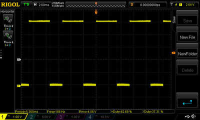
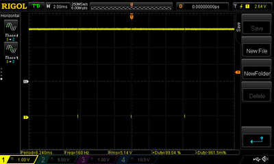
I have an Arduino board here and it is programmed according to the code from the above video. When I check the signal with the oscilloscope I see PWM variation and no significant frequency variation. See both pictures below with the potentiometer set to MIN and MAX.
Can someone explain to me how this works?
Hi @richardmcv,
Welcome to the forum!
Your question has a little ambiguity, in that controllers like the one you mention are playing more than 1 'trick' at a time, and it is unclear which of the tricks is confusing you. So rather than give a long explanation, perhaps I can mention the two obvious 'tricks' and invite you to comment.
- Stepper motor
- PWM
Stepper motors have stator and rotor physical construction such that they move in step of a fixed angle increment. Each step position requires a particular combination of powered and unpowered windings, and moving a step involves changing that combination.
A simple system will cause the rotor to rotate by repetitively changing the combinations of powered and unpowered windings in the appropriate sequence and at a rate that the rotor can physically keep up with. At any moment of time, the voltage applied to each winding is either 'zero' or 'full'.
The simple system has the advantage of minimal electronics cost, but the motion of the rotor can be rather 'cog-like' as it snaps from one step position to the next.
To minimise the 'cogging', it is possible to 'soften' the power transitions such that the power is 'gradually' switches from zero to full (and full to zero). Careful timing and 'shaping' of these transitions can provide a much smoother and quieter motion. (Other 'shaping' for power saving, etc. may also be deployed.)
In principle, the 'shaping' could be achieved by an analogue current amplifier circuit, but this would be very inefficient as the amplifier would need to waste a large proportion of the electrical power as heat.
Hence, the principle of PWM is introduced. The general outline of the stepper motor power sequencing is maintained, but a high frequency (i.e. much higher frequency than the step sequencing) switching is superimposed, so that at any moment that a winding is in the 'power on' part of the sequence, the applied voltage is switching between zero and full. The 'average' power applied is controlled by varying the ratio of time that it is 'on' and 'off'.
This discussion maybe oversimplified, but I hope it helps a little. If you have more specific questions, there are a number of contributors on this forum with hands-on expertise.
Good evening DaveE,
Thank you very much for your explanation. The principle of the stepper motor is clear to me, as is the principle of the average power with a varying Duty Cycle.
The confusion arises because the specifications of the MA860H state that the pulse frequency may vary between 0 and 100 kHz.
That's why I expected to need a square wave with a duty cycle of 50% that can be adjusted in frequency.
Hi @richardmcv,
I don't know the particular controller, so there may be some 'magic' that others might be able to help you with. What would a 50% square wave of variable frequency would be useful for?
The most obvious relationships of frequency would be the combination of the change of the stepping speed and the associated PWM modulation which obviously must be must faster than the stepping speed to be useful to modulate the step power drive. Of course, it is necessary to change the duty cycle to achieve the modulation - changing the frequency doesn't affect the 'average' power.
Best wishes.
First of all: best wishes to all!
I've some questions about the used sketch in the YouTube movie (Big Stepper Motors with Arduino) about the MA860H driver.
First question> there's a line that maps the potentiometer value. 0-1023 will be converted to 2000-50. This means if the potentiometer is at MIN, the motor is stil turning. What value can I put in so that the motor stands still at potentiometer=MIN?
Second question> there's a line: boolean setdir=LOW
So at every startup I have the same direction. Since I do not need two directions, what should I do: change the value to HIGH if the direction is fault? Or connect the DIR- of the driver to ground?
(if I look on top of the shaft, it has to turn CCW; CW should not occur)
Happy New Years to you as well @richardmcv,
As I'm not familiar with this MA860H driver board, I can't tell you if connecting the DIR of the driver board to ground can be done.. but as a practical matter , it should be considered..This will also dispose of some software code that won't be needed, if your sure that you won't need to be able to change the direction in the future. At any rate, I wish you success in solving your problem, and to see what you have done to mitigate it.
Regards,
LouisR
LouisR
I've some questions about the used sketch in the YouTube movie (Big Stepper Motors with Arduino) about the MA860H driver.
First question> there's a line that maps the potentiometer value. 0-1023 will be converted to 2000-50. This means if the potentiometer is at MIN, the motor is stil turning. What value can I put in so that the motor stands still at potentiometer=MIN?
Try zero, but be aware that most pots aren't that precise or stable. You may need to change your range of pot values from 0-1023 to something like 10-1023 to make sure it actually has a "zero" reading.
Second question> there's a line: boolean setdir=LOW
So at every startup I have the same direction. Since I do not need two directions, what should I do: change the value to HIGH if the direction is fault? Or connect the DIR- of the driver to ground?
Try connecting the DIR pin to GND through a 10K resistor to see if that works, if not, then connect the pins directly. The 10K resistor will tie the pin to ground, but will limit current flow. If the DIR pin is already tied HIGH internally, then connecting it directly to GND should be OK.
Anything seems possible when you don't know what you're talking about.
Hi all,
I have no knowledge of this kit, but a quick Google picked up a manual
http://www.gbeshop.com/infobase/downloads/ma860h-n_user-manual-en.pdf (I assume this is the right manual?)
which includes:
At first glance (please check carefully yourself--I may have missed something - I usually do!)
-----------------------
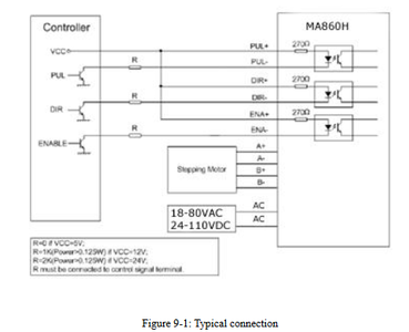
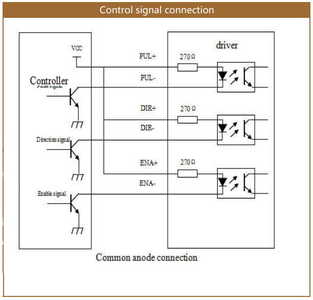
ASSUMING YOU HAVE VCC connected to 5V, then you do not need resistors, just direct wires (as explained on the circuit diagram note)
And
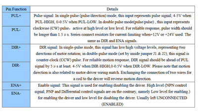
The text says DIR expects to be connected to 5V or 0V, but which one corresponds to which direction seems to be down to try it and see. As you only want one direction, luckily you do not need to worry about the timing requirements.
You need to decide whether to control DIR by either of these two schemes:
- connecting to your (Arduino) controller and setting the Arduino pin 'High' or 'Low' as desired
- connecting the DIR pin to ground for 'Low' and disconnected for 'High'
DO NOT DO BOTH SCHEMES ... you will get confused and your Arduino pin will not like being shorted to ground, if it has been set to high.
--------------------
Further explanation:
Looking at the circuit diagram shows the MA860 interface is via an opto coupler which requires a current to flow through the opto coupler LED to actvate it, when the drive is low (0V).
Leaving DIR disconnected, is effectively the same as connecting it to 5V ... either way the current through the LED will be zero.
(A 10k pull up will do nothing and a 10k pull down is probably too high a value to do anything.)
----------------------
Happy New Year folks! Dave
@Inst-Tech:
I'm very sure that I won't need the second direction in this case, so some code can be removed from the original sketch. But since I've only just stepped into the wonderful world of Arduino, I don't know exactly which code yet. It is of course only a small program so I have no problem with the extra code. I do agree with you that an effort should be made to keep a program as clean as possible.
@Will:
Setting the value to zero feels a bit strange. Since the value 0 is lower than the value 50 in the program you would think you would then set the motor speed to maximum, right?
I expanded the code today so that I can read the value of the potentiometer in VOLTS on the serial monitor. The serial monitor shows that:
Potentiometer in MIN position shows a value of 0.00
Potentiometer in MAX position shows a value of 5.00
So the potentiometer seems pretty accurate. But indeed it is an idea to adjust the range of the potentiometer.
According to the original manual of the driver, both the DIR, PUL and the ENA connection have an optocoupler that I can supply with 5 volts without needing an extra resistor.
A built-in 270 ohm resistor is already present for current limiting. When connecting a voltage higher than 5V, an extra resistor must be placed. There is no harm in testing with an extra resistance of 10Kohm.
Funny detail: The ENA works exactly the other way around than I expected. As soon as I plug it in, the motor will NOT turn! It took me quite some time to figure this out. I expected that the ENA must always be present in order to keep the motor running.
The supplier here in the Netherlands could not provide me with a manual of the driver. I had to request this from the factory in China. After reading this manual it turned out that the ENA should not be connected.
Thanks @davee for explaining the details of the DIR connection.
I assumed (bad habit) that the 2000-50 was motor speed, but it appears that it may be inter-step time. However, that would imply that the motor could never be stopped unless the inter-step time was set infinite.
Perhaps you could try some larger value (like 5000) to see if that slowed or stopped the motor enough for your needs. If it does, you could try setting the speed like
if (potVal<10) {
speed = 5000; // 10000, 20000 - whatever works best for you
// digitalWrite(ENAPin,HIGH); // Alternative to stop motor using pin connected to ENA
} else {
speed = map( potVal,10,1023,2000,50);
}
so that very low pot values are set to whatever it takes to shut down the motor (maybe even setting ENA HIGH) and higher values map into the same range as before.
Anything seems possible when you don't know what you're talking about.
To be sure which signal the MA860H stepper motor driver needs to function, I contacted the factory. After all, it was not clear whether it had to be a PWM signal or a signal that varies in frequency.
I have received the following response from the factory:
Dear Sir
My name is Michelle, I will be responsible to solve your questions.
DM860H is a stepper motor driver.
It is a square wave with a Duty Cycle of 50% whose frequency is varied to give a different speed to the motor.
If you have any questions, please contact us.
With Regards
Best Wishes | 此致 敬礼
Hi @richardmcv,
Apologies if my first reply was confusing .. I haven't seen the particular video but I assumed your reference to PWM referred to the 'enhanced' way of driving a stepper motor to reduce the 'cogging' effect. That is the drive for a single step of the motor is split into multiple PWM pulses to 'shape' the power applied.
I haven't worked on this personally, but I can imagine the acceleration and deceleration of the rotor whilst achieving each step could be reduced, especially when the motor is being repetitively stepped, thereby giving a smoother motion. Similarly, the power applied to maintain the position of the rotor at a particular angle is probably be less than needed to move the rotor, so PWM could be used to save average power consumption and reduce heating whilst the rotor is stationary.
It seems that the signal you queried with the manufacturer corresponds to the 'basic' step function (which does not involve PWM) ... that is one pulse corresponds to a step (or maybe half/quarter/... step in some cases?) to move the rotor to then next position. Perhaps this controller does not support the PWM 'enhancement' case?
Best wishes, Dave
Hi @ DaveE
In my situation the stepper motor is used in the simplest setup. The drive is supplied with voltage with a push button (with a relay with hold function). Then the motor is set with a potentiometer to a desired speed. There is only one direction of rotation: counterclockwise.
During the first test, the motor did run because a signal was applied to the driver. This signal had a certain frequency that the driver could handle.
But because the driver needed a frequency based signal, it did not respond to the variation in pulse width.
The program has therefore become simple. With the MAP function the signal of the potentiometer is converted. Then the output 13 is switched on/off with digitalWrite and delayMicroseconds.
If I now turn the potentiometer, I get a square wave that is reasonably close to 50%.
The drive is now set to 800 pulse/revolution and works quite well with this. Only problem at the moment: If I switch on the drive while the potentiometer is set to maximum, it sometimes happens that the motor does not turn but only makes noise. If I turn the potentiometer back slightly, the motor will start running. Another thing to find a solution for...
Hi @richardmcv,
Good to hear that you are making progress.
With regard to your last paragraph/problem - I offer the following as my imagination of what may be happening and where to look for a solution.
You will know stepper motors move from one fixed angle position (let's call it "FP1") to the next fixed angle position (FP2), and then FP3, FP4 and so on.
Thus if it is at stationary at FP1, and using the controller change the applied power to move to the FP2 position, then the rotor will start to move to the FP2 position, but as the rotor is starting from stationary, it will take some time to move to FP2, as it accelerates.
If the controller then changes the power to that appropriate for the FP3 position, BEFORE the rotor has moved from FP1 to FP2, then it may return to the FP1 position.
This process can continue indefinitely, probably causing the rotor to 'shiver' between two adajacent positions, which would be the source of the noise you observe.
The simplest solution is probably to reduce the maximum pulse/step rate, so the motor always has 'time' to move to move to the next position. However, this may mean the system is slower than you would like. In addition, if you pick a rate which is only just below limit, you may find small changes of friction, etc. are enough to cause the effect to reappear.
-----------
I can only guess what your system looks like. You may be able to do a software fix.
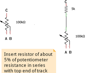
Alternately, if you simply want to prevent the user picking the maximum position on the potentiometer, then a common trick is to add a resistor in series with the track of the potentiometer.
i.e. assuming the potentiometer on the left is your present potentiometer, then insert a resistor in series with the top of track connection as shown on the right. The value of the resistor depends upon the potentiometer resistance. At a first guess, I would aim for 5% of potentiometer resistor, as illustrated assuming pot was a 100kOhm, but some experimentation may be required.
-------------
The 'smarter' controllers vary the pulse rate to compensate for this problem, so that the motor accelerates, and also decelerates if its inertia at maximum speed would cause it to overshoot. You might consider this as a future direction.
Hope this helps. Good luck with your investigation. Dave

