Interesting approach to try and solve it with two magnetometers! I would guess that they would be both too slow and too imprecise to give a useful reading, but I might be wrong.
What you could do is create your own 'servo', connect a motor shaft to a potentiometer of your own, and write some code to find the position.
Speed wouldn't be an issue. This is only required during the boot up phase.
- Get a reading on both mags.
- Calculate the angle of the head and rotate it.
- Double-check the readings. Should be right the first time, but if not go to #1.
- From then on, the MPU knows where zero is and the stepper just rotates to desired angles. There is not run-time need for the mag's for head position any longer.
As far a precision, each component is on the Magnetometer is a 16 bit integer. That gives better than 4 decimal places on an angle. Although sensor signal noise will probably be barely degree accurate.
However, you do have a good point on the potentiometer and the bigger stepper I resorting to has plenty of torque to turn it. BUT... hooking it up to an analog pin of only 10 bits is likely to have its own precision issues. But, it will be a good fallback position. Thanks.
VBR,
Inq
3 lines of code = InqPortal = Complete IoT, App, Web Server w/ GUI Admin Client, WiFi Manager, Drag & Drop File Manager, OTA, Performance Metrics, Web Socket Comms, Easy App API, All running on ESP8266...
Even usable on ESP-01S - Quickest Start Guide
@robotbuilder - I have several magnetometers... some are just 3-axis, standalone and some are in combination with accel, and gyros. I haven't got to the point of hooking them up yet. I guess... I'm mainly recalling a lot of phone apps want you to wave your phone around in three axes in an infinity shape to "calibrate" them.
I'm not about to pick up the robot and start swinging it around my head. People will send for the strait jackets.
VBR,
Inq
3 lines of code = InqPortal = Complete IoT, App, Web Server w/ GUI Admin Client, WiFi Manager, Drag & Drop File Manager, OTA, Performance Metrics, Web Socket Comms, Easy App API, All running on ESP8266...
Even usable on ESP-01S - Quickest Start Guide
I'm not about to pick up the robot and start swinging it around my head. People will send for the strait jackets.
I wasn't suggesting you do that. I did a google and there are videos on using such sensors and reading the data to the Arduino IDE to get an idea of the data you would have to work with. I assume the idea is to match the data with the laser data.
The dual-magnetometer idea (one in body, one in head) has two purposes.
1. Initializing Head Centered
Using the standard servos, when the bot boots up, the servo is told to go to 90 degrees and the head is facing forward. No intervention is ever needed after the assembly. Not so with a stepper or one of these continuous servos. We have no idea when the bot was turned off where the head was pointing. When it powers up, we have to find "strait ahead".
So... I'm suggesting at boot up, the head stepper is rotated until the head Mag is the same as the body Mag.
The comment about the phone apps saying they need to be "calibrated" by swinging them around is my lack of understanding...
- If the two mags are physically pointing in the same direction can they be showing drastically different results because they are not calibrated?
OR
- Or will they be showing the same values... but these may not coincide with Earth's Magnetic North?
2. Normalizing the Laser Data
The second part is a second use of the sensor and has nothing to do with the head alignment. This is just something that I've never heard of before, but just a WAG to see if it might help.
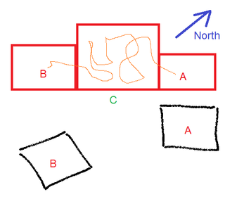
- Say the robot is at "A" in the real house (represented in Red below).
- It does a 360 scan and gets the data as represented at "A" in the black scatter data.
- It moves point "B" in another room through some convoluted path and has built up too much error in the dead-reckoning mode.
- It'll get the relative distances of the rectangular walls in "B", but they will be all rotated by some value.
I'm hoping that by using Magnetometer value as part of the data, that I can re-align at least the orientation of room "B" to be consistent with the room "A".
*** Still don't have a solid theory about offsets of walls. I'm hoping that continuity of building up the map will allow me to say...
"This bottom wall at A is parallel and about in the same position as the bottom wall at B... and that I'll be able to estimate that they are in fact a continuation wall as marked by C in the real-world."
Don't know... but it will be a learning experience when I get to that point.
VBR,
Inq
3 lines of code = InqPortal = Complete IoT, App, Web Server w/ GUI Admin Client, WiFi Manager, Drag & Drop File Manager, OTA, Performance Metrics, Web Socket Comms, Easy App API, All running on ESP8266...
Even usable on ESP-01S - Quickest Start Guide
So... I'm suggesting at boot up, the head stepper is rotated until the head Mag is the same as the body Mag.
It might be simpler to just rotate the stepper until a position sensor at the front of the robot is triggered?
The comment about the phone apps saying they need to be "calibrated" by swinging them around is my lack of understanding...
I don't understand exactly how the apps work or what internal sensors they use I just found them interesting to play with.
To enlarge an image, right click image and choose Open link in new window.
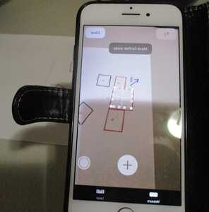
The mobile phone is a powerful computer with many sensors and could be used as a robot brain.
As regards normalizing the laser data you need to study it to figure out how you would do it yourself if you were inside the robot and that was the only data you had. It is useful to imagine you are inside the robot and have control of the motors but only have the data provided by the robot's sensors.
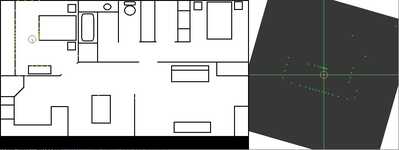
Looking at the simulated data with steps of 10 degrees to make the dots more obvious you can see that closer walls have more dots which concentrate at the closest point to the robot. Distant wall have less dots more evenly spaced. You could process these images to extract lines and their orientation and where they might meet at corners and so on.
To enlarge image, right click image and choose Open link in new window.
The mobile phone is a powerful computer with many sensors and could be used as a robot brain.
OpenBot.org - Setting a very high bar! Not many (any?) robots on the forum can match that capability. It takes a quite a bit of work to do that with our own MPU and sensors.
3 lines of code = InqPortal = Complete IoT, App, Web Server w/ GUI Admin Client, WiFi Manager, Drag & Drop File Manager, OTA, Performance Metrics, Web Socket Comms, Easy App API, All running on ESP8266...
Even usable on ESP-01S - Quickest Start Guide


