I'm finding my Servos only do 0 to 120. Even when the Stepper.h tells them to do 0 to 180. I'd like 0 to 360. It is my understanding that regular servos have a potentiometer in them. That sending a particular frequency of PWM to them sends them to a specific position as confirmed by the resistance of the Pot.
So... how do these "360 Degree Continuous Rotation" servos work?
- Some of the advertisements even show wheels on them... so not only 360, but a million degrees???
- A Pot isn't going to have 360 rotation. And even if it did, wouldn't its resistance cycle instead of getting continuously smaller or larger?
- How do we tell it to go to 700 degrees.
- Does this use the standard Stepper or FastAccelStepper library?
- How do we tell it to do 1000 revolutions?
- They also seem to be a lot more expensive. Is that because of more expensive/complicated electronics to do the stuff above instead of a pot OR is it simply economy of mass production (ie. they make 1000:1 of the standard models)?
Thanks for your help.
VBR,
Inq
3 lines of code = InqPortal = Complete IoT, App, Web Server w/ GUI Admin Client, WiFi Manager, Drag & Drop File Manager, OTA, Performance Metrics, Web Socket Comms, Easy App API, All running on ESP8266...
Even usable on ESP-01S - Quickest Start Guide
Perhaps instead of pots, they are using something like a slotted wheel and a light sensor to count pulses.
First computer 1959. Retired from my own computer company 2004.
Hardware - Expert in 1401, and 360, fairly knowledge in PC plus numerous MPU's and MCU's
Major Languages - Machine language, 360 Macro Assembler, Intel Assembler, PL/I and PL1, Pascal, Basic, C plus numerous job control and scripting languages.
Sure you can learn to be a programmer, it will take the same amount of time for me to learn to be a Doctor.
I found this https://www.pololu.com/category/143/continuous-rotation-servos that indicates that when they modify them for continuous, they no longer can be positioned. The PWM setting defines the speed it runs, not the position. Sounds like these won't help me do a 360 degree owl type robot neck... I can't define a position of zero or +180 or -180.
3 lines of code = InqPortal = Complete IoT, App, Web Server w/ GUI Admin Client, WiFi Manager, Drag & Drop File Manager, OTA, Performance Metrics, Web Socket Comms, Easy App API, All running on ESP8266...
Even usable on ESP-01S - Quickest Start Guide
@inq Why not, you will need a calibration step perhaps only once at power up or maybe periodically. Maybe even automate it by installing a sensor like a photodiode and a tightly focused light, one on the fixed part, one on the moving part to re-calibrate periodically. OR I have completely misunderstood yet again, it's been that kind of week.
First computer 1959. Retired from my own computer company 2004.
Hardware - Expert in 1401, and 360, fairly knowledge in PC plus numerous MPU's and MCU's
Major Languages - Machine language, 360 Macro Assembler, Intel Assembler, PL/I and PL1, Pascal, Basic, C plus numerous job control and scripting languages.
Sure you can learn to be a programmer, it will take the same amount of time for me to learn to be a Doctor.
Maybe you have a clearer understanding, but these continuous servos sound almost like regular motors. Even if I make a way of setting it to zero degrees, setting a PWM frequency... makes it move at a continuous rate. I guess I could use some micros() for timing how many degrees it moved and stop it, but that seems likes way complicated versus a regular servo that you simply say... go to 90 degrees.
I was hoping someone had actually used one of these kinds of servos and knew how they were controlled. Even the Internet sources I've found so far seem to indicated that these are controlled by speed... not position.
3 lines of code = InqPortal = Complete IoT, App, Web Server w/ GUI Admin Client, WiFi Manager, Drag & Drop File Manager, OTA, Performance Metrics, Web Socket Comms, Easy App API, All running on ESP8266...
Even usable on ESP-01S - Quickest Start Guide
Why not just hack up an encoder and maintain a running count the pulses as you go. You already know if you're going clockwise or widdershins, so just add 1 for every pulse one way and subtract one for every pulse the other direction.
You can then figure the angle (or distance) as the proportion of (pulse count)/(pulses per revolution).
Anything seems possible when you don't know what you're talking about.
Why not just hack up an encoder and maintain a running count the pulses as you go. You already know if you're going clockwise or widdershins, so just add 1 for every pulse one way and subtract one for every pulse the other direction.
You can then figure the angle (or distance) as the proportion of (pulse count)/(pulses per revolution).
@will - I'm not sure I'm have the know-how to hacking a reliable encoder. The mechanical side alone would seem fragile and inaccurate. I'm picturing something like the guts in an old mouse... LED, light sensor, little rotating grate. Do you have something easier in mind?
What I thought was a simple want has turned into a big Snafu. All I wanted was to have a well-defined way of scanning a 360 neck for my robot. I want to just drive it into a room and then owl neck around to get a 360 degree 3D mapping. All my servos are 120 to 180 degrees. I switch to the little micro-stepper motor, but even with 1:5 gearing, its barely strong enough to overcome my 3D printed gearing. I don't have much hope for it, long term.
That's when I checked Amazon to see if there were servos with greater than 180 degree turning. Low and behold, yes, but they are all turning out to be this continuous kind that isn't the simple PWM controlled placement.
Last night I flipped again back to steppers using one of these cheap 28BYJ-48 stepper motors. They're relatively huge for the need, but at $3 I live with crude-overkill. I found how to hack it to use it with an A4988 stepper driver and have fined tuned the current so it doesn't heat up like it did on the Inqling Sr. robot.
3 lines of code = InqPortal = Complete IoT, App, Web Server w/ GUI Admin Client, WiFi Manager, Drag & Drop File Manager, OTA, Performance Metrics, Web Socket Comms, Easy App API, All running on ESP8266...
Even usable on ESP-01S - Quickest Start Guide
It would normally require a 3D printed disk (with holes at regular intervals around the outside) that would fit over the shaft of your rotor. You'd mount a sensor like something from Amazon "Slot Type IR Optocoupler Speed Sensor Module LM393 for Arduino" at the outer edge to sense the holes as it rotates and some Arduino connections for power and sensing.
Since you already have a solution with the BYJ steppers, I'd say just stick with that until it becomes unsatisfactory (if it ever does :))
Anything seems possible when you don't know what you're talking about.
Remember in a continuously turning base you have the issue of connecting wires to the sensor.
From dronebot workshop lidar article,
One very nice feature of the RPLIDAR is that it does not use a slip-ring to make connections to the LIDAR laser transmitter and receiver on the revolving platform. Instead it uses proprietary wireless and optical connection, eliminating a potential point of electrical failure and/or data corruption.
You could place a magnet on the rotating platform and use it to trigger a hall effect sensor for a complete rotation or an optic sensor to detect a hole in the rotating platform. The position (degrees) would be a function of time since the last pulse. You would set the rotation speed to match the rate of data acquisition from the sensor.
Remember in a continuously turning base you have the issue of connecting wires to the sensor.
I haven't done an exhaustive search, but it seems I can only find servos that:
- range somewhere between 120 and 180 degrees. These use PWM to tell to go to an exact position. If I could find a servo that could use this control method and do a full 360, that would be optimum.
- continuous range. These use PWM to tell what speed to do. Position information is unavailable / uncontrollable unless, I add some encoder hardware / software as @will suggested. I would also have to constrain this to only the 360 degrees as to not run into the wiring winding up issue.
It just seems like my choices are: it's easy to implement with insufficient range OR a big PITA.
You could place a magnet on the rotating platform and use it to trigger a hall effect sensor for a complete rotation or an optic sensor to detect a hole in the rotating platform. The position (degrees) would be a function of time since the last pulse. You would set the rotation speed to match the rate of data acquisition from the sensor.
My current thought (unless someone say's I'm delusional) is to use a second 3-axis magnetometer in the head. I've not used these things before, but it is my hope that I could use one in the body to get body orientation WRT the world and a second one in the head that also get its orientation WRT the world. In my thinking, I can solve several things with this configuration:
- When I align the orientations of the both sensors, I'll know that the head is pointed the same direction as the body... ie the head is pointed centered and pointed forward.
- If they are not both pointed in the same direction, the relative angles defined by the two magnetometers will tell me which way to turn the head to bring them into alignment. I don't have to move to a stop and then move to a calculated center.
- Having a second one in the head gives me a more direct way of transforming the scanned data into a global Cartesian coordinate system before storage. If I just have the one in the body, I'd also have to transform the relative head position.
Does this sound logical AND feasible or is there something about magnetometers that will be unreliable? I'm thinking mainly... is the Earth's magnetic field strong enough to overcome local disturbances and will a servo or stepper motor nearby totally confuse the magnetometer? Another Science experiment awaits.
VBR,
Inq
3 lines of code = InqPortal = Complete IoT, App, Web Server w/ GUI Admin Client, WiFi Manager, Drag & Drop File Manager, OTA, Performance Metrics, Web Socket Comms, Easy App API, All running on ESP8266...
Even usable on ESP-01S - Quickest Start Guide
@inq I would run the experiment but I expect local influences will override the earth. IIRC that is why old ships with compasses had 2 iron balls beside them to adjust for the metal in the ship.
First computer 1959. Retired from my own computer company 2004.
Hardware - Expert in 1401, and 360, fairly knowledge in PC plus numerous MPU's and MCU's
Major Languages - Machine language, 360 Macro Assembler, Intel Assembler, PL/I and PL1, Pascal, Basic, C plus numerous job control and scripting languages.
Sure you can learn to be a programmer, it will take the same amount of time for me to learn to be a Doctor.
IIRC that is why old ships with compasses had 2 iron balls beside them to adjust for the metal in the ship.
Hmmm... I must be all wrong, I was thinking Inqling needed brass ones.
3 lines of code = InqPortal = Complete IoT, App, Web Server w/ GUI Admin Client, WiFi Manager, Drag & Drop File Manager, OTA, Performance Metrics, Web Socket Comms, Easy App API, All running on ESP8266...
Even usable on ESP-01S - Quickest Start Guide
Hmmm... I must be all wrong, I was thinking Inqling needed brass ones.
Don't use brass, their performance "drops off" in cold weather:)
Anything seems possible when you don't know what you're talking about.
Cheap continuous servos are, as far as I know and as far as I've seen them used, just normal geared down motors in servo motor form factors and do not provide any position information.
Interesting approach to try and solve it with two magnetometers! I would guess that they would be both too slow and too imprecise to give a useful reading, but I might be wrong.
What you could do is create your own 'servo', connect a motor shaft to a potentiometer of your own, and write some code to find the position. That way you can either gear down the rotation from the shaft to the pot or get a 10 turn pot to get more turns than your usual servos. Another option is to use a continuously rotating pot. Those are rare, but they do exist. I believe they consist of 2 potentiometers in one, on the same axis but flipped 180 degrees, so that if one is in the 'dead zone' the other still can have a reading.
Good luck!
My current thought (unless someone say's I'm delusional) is to use a second 3-axis magnetometer in the head.
Only one way to find out!! Hook a 3-axis magnetometer sensor to an Arduino and find the library to use it.
They are probably used in drones which have a swivelling camera and also have to remain at some orientation at each point in time depending on what it is doing.
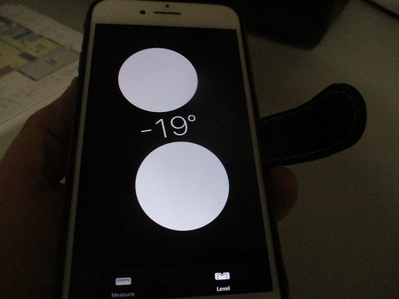
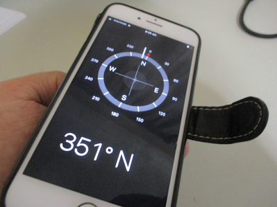
My iphone seems to know its orientation in 3d space (flip photos to keep them upright for viewing).
There may be a project using an Arduino that does exactly the same thing using a LCD display HAT.
To enlarge an image, right click image and choose Open link in new window.


