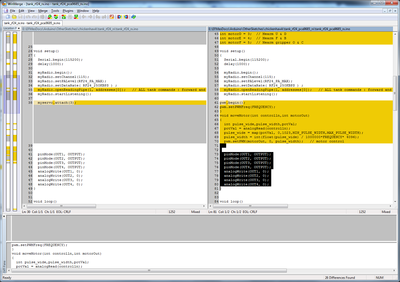
I think I found the problem, but I would like to hear from anyone following this. This line I think.
myRadio.write(&data,sizeof(data)); Transmitter side
myRadio.read(&data,sizeof(data)), Receiver side
These lines" write" the data from the joystick (transmitter) and "read" the date for the (receiver)????
Because the is no "write or read" for the potentiometer/servo side I have no movement of the servo.
Yes/No ??????
I think "No" ?
You are actually transmitting a data structure of type Package, which contains X, Y and servo
So, to help you I'll need to compile scripts, even though I don't have RF24's with me...
Is it the library you are using ?
Eric
Eric
Also I hope you're aware of that and your receiver is a Mega, otherwise you'll have to leave pins 9+10 alone :
On boards other than the Mega, use of the library disables analogWrite() (PWM) functionality on pins 9 and 10, whether or not there is a Servo on those pins.
From the Servo library reference here : https://www.arduino.cc/en/Reference/Servo
Eric
Uploaded tank_fr24_rx.ino and tank_rf24_tx.ino to each of the 2560 mega. When I hooked the transmitter to the serial monitor all outputs are correct. Removed this line from the TX sketch:
//myRadio.write(&data,sizeof(data));
Hooked up the receiver to the serial monitor and it shows nothing
This line in the TX sketch was aready commented (with the leading "//") so it was not executed, leaving only the serial monitor output to verify you actually see your inputs as you play with the joysticks/potentiometers
If you want the Mega witht the TX sketch to actually transmit anything, you must not remove this line but un-comment it !
So put it back in the TX sketch and just remove the "//" at the beginning of that line.
Then you'll be able to check what the RX sketch shows on its serial monitor.
In the Arduino IDE (in fact in a C or C++ program), things on a line after "//" are just comments.
Eric
Sorry been up all night, will start again when my head is clear
Transmitter side on serial monitor works great " x " --"y"--and servo1 shows they are transmitting data.
Receiver side on serial monitor shows that it is receiving data.
Rov moves forward/back-right/left but no movement on the servo when potentiometer is turned, checked power supply to servo and it is good and changed servo and no movement
Hum I would do a simple potentiometer+servo sketch on the receiving Mega (with no motor or radio) just to test the servo and pin 3 are actually ok.
If yes, then there may be some timer conflict issue between the timer used by Servo and the PWM used for the motors ?
Eric
Well after uploading a knob sketch it still did not work, so I unwired the servo from the buck converter and wired the servo right to the Arduino board. Worked great, so I stopped had a coffee and had a hard think about things. I then realized in my hurry I had forgot to add a extra ground from the buck converter/servo back to the Arduino board, added the ground and uploaded the sketches again. WORKS GREAT!!!!!!!! Just shows that not all problems are with programing. Now my grandson has decide that we should add a Mearm to the front of the ROV so now he is off to order a PCA9685 servo driver. We will take the next 15 days waiting for the servo driver to come in to study the sketches line by line to fully understand what each line does.
Many many thanks ZeFerby for you help
Ok first, let's go back to Bill's sample code :
You can see that void moveMotor(int controlIn, int motorOut) is a utility function that is called once for each servo in void loop(), and this function applies a PWM value after it reads a potentiometer value with this line of code :
potVal = digitalRead(controlIn);
Now your base concept is that the tank would not physically have 1 potentiometer for each servo, but would receive potentiometer values through the radio link.
So adapting Bill's code to integrate it into your sketch means :
- keeping the void moveMotor(int controlIn, int motorOut) utility function
- slightly changing the void moveMotor function so that it can use a value provided from the sketch instead of reading a potentiometer
- implementing the code that calls moveMotor in a place where the values received through the RF24 are already available
- ...and of course get the servo values through the RF24 link in the first place...
Now let's move to your skecth above, and try to check each of these 4 points :
Point 1 :keeping the void moveMotor(int controlIn, int motorOut) utility function
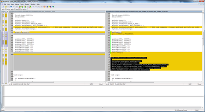
Here is the comparison between the previous version of the sketch (on the left side, tank_rf24_rx.ino) and your sketch above (right side, tank_rf24_pca9685_rx.ino) :
I see a problem with how void moveMotor was inserted in the sketch :
the last initialization lines of the void setup() function are now at the end of void moveMotor(), so every time moveMotor would be called, it would also apply pinMode and then analogWrite a 0 to OUT1-OUT4, which is the startup code with the tanks motors stopped !
So let's correct that by moving back those lines where they belong in void setup(). We'll also add some cosmetic changes (proper alignment, function names in comments after closing braces) :
Point 2 : slightly changing the void moveMotor function so that it can use a value provided from the sketch instead of reading a potentiometer
This is easy : we want moveMotor to directly use a potentiometer value, taken as a parameter, instead of getting an analog pin number as parameter and reading its value.
So let's change :
void moveMotor(int controlln,int motorOut)
{
  int pulse_wide,pulse_width,potVal;
  potVal = analogRead(controlln);
  pulse_wide = map(potVal, 0,1023,MIN_PULSE_WIDTH,MAX_PULSE_WIDTH);
  ...etc...
to :
void moveMotor(int potVal,int motorOut)
{
  int pulse_wide,pulse_width;
  pulse_wide = map(potVal, 0,1023,MIN_PULSE_WIDTH,MAX_PULSE_WIDTH);
  ...etc...
...and that's it !
Point 3 : implementing the code that callsmoveMotor in a place where the values received through the RF24 are already available
Of course the void applyTankCommands() function is a good spot to choose, where you now have a "line of slashes" replacing the previous myservo.write(val); :
But you have an issue here : different variables, defined in different scopes, having the same name.
- motorA to motorF are defined and initialized in the global scope of the sketch just before void setup() for the PCA9685 output port numbers of the servos :
// Define Motor Outputs on PCA8685 board

int motorA = 0; // Camera pan
int motorB = 1; // Camera tilt
int motorC = 2; // Mearm R & L
int motorD = 3; // Mearm U & D
int motorE = 4; // Mearm F & B
int motorF = 5; // Mearm gripper O & C
- but now, within the scope of void applyTankCommands(), you have new variables with the same names, which contain the pot values for the servos :
int motorA = data.motorA; // Camera pan potentiometer 1
int motorB = data.motorB; // Camera tilt potentiometer 2
int motorC = data.motorC; // Mearm L & R joystick 2
int motorD = data.motorD; // Mearm U & D joystick 2
int motorE = data.motorE; // Mearm F & B joystick 3
int motorF = data.motorF; // Mearm gripper O & C joystick 3
(and you also have the same names used as members of the typedef struct Package, but that is ok because you only use them with "data.motorXXX").
==> the global variables motorA to motorF (PCA port numbers) are "hidden" by the local ones (pot values) inside void applyTankCommands()
But if you want to call moveMotor(int potVal, int motorOut) for the servos, you need to access BOTH the pot value AND the PCA9685 port number for each servo, so how can you do that ?
Well, there is a solution using the C++ double colon "scope resolution operator" (::) but I won't go into that...
I think the best thing to do, as it makes the sketch easier to understand and less error-prone to maintain, is to use different names for the variables, for example :
- rename the global (PCA968 port numbers) motorXXX variables to motorXXXport :
// Define Motor Outputs on PCA8685 board

int motorAport = 0; // Camera pan
int motorBport = 1; // Camera tilt
int motorCport = 2; // Mearm R & L
int motorDport = 3; // Mearm U & D
int motorEport = 4; // Mearm F & B
int motorFport = 5; // Mearm gripper O & C
- rename the local (pot values) motorXXX variables to motorXXXval in void applyTankCommand :
int motorAval = data.motorA; // Camera pan potentiometer 1
int motorBval = data.motorB; // Camera tilt potentiometer 2
int motorCval = data.motorC; // Mearm L & R joystick 2
int motorDval = data.motorD; // Mearm U & D joystick 2
int motorEval = data.motorE; // Mearm F & B joystick 3
int motorFval = data.motorF; // Mearm gripper O & C joystick 3
Then you can insert a block like this one where you currently have the "line of slashes", which will implement servo positionning :
moveMotor(motorAval, motorAport);
moveMotor(motorBval, motorBport);
moveMotor(motorCval, motorCport);
moveMotor(motorDval, motorDport);
moveMotor(motorEval, motorEport);
moveMotor(motorFval, motorFport);
which gives something like :
void applyTankCommands() {
  int X = data.X; // Tank forward & back
  int Y = data.Y; // Tank left & right
  int motorAval = data.motorA; // Camera pan potentiometer 1
  int motorBval = data.motorB; // Camera tilt potentiometer 2
  int motorCval = data.motorC; // Mearm L & R joystick 2
  int motorDval = data.motorD; // Mearm U & D joystick 2
  int motorEval = data.motorE; // Mearm F & B joystick 3
  int motorFval = data.motorF; // Mearm gripper O & C joystick 3

  int foward = map(X, 524, 1024, 0, 255); // Tank
  int backward = map(X, 500, 0, 0, 255); // Tank
  int right = map(Y, 524, 1024, 0, 255); // Tank
  int left = map(Y, 500, 0, 0, 255); // Tank

  moveMotor(motorAval, motorAport);
  moveMotor(motorBval, motorBport);
  moveMotor(motorCval, motorCport);
  moveMotor(motorDval, motorDport);
  moveMotor(motorEval, motorEport);
  moveMotor(motorFval, motorFport);

  if (X > 524 && Y < 524 && Y > 500) {
...etc...
Point 4 : ...and of course get the servo values through the RF24 link in the first place...
That has been done nicely ! The rest of Bill's code required #includes and #define constants are also well integrated to your sketch.
(I only slightly changed the printed labels in void printReceivedData() to increase the readability).
So here is my edited version of your script above :
Eric
When I can get all 3 boys together they can go through all of this.
Well the boys had a giant crash, they somehow deleted the whole transmitter sketch. They are going to try to start over and rewrite it.


