@headingholder - I was really hoping if I plug in some user's handles, we'd get some expert help. I'm also glad you went with the ESC! @zander's came in with some great drawings, I'd not seen before that are the perfect description of what I had imagined was possible. And I knew if @davee took up the opportunity, he'd deliver the details that give us real insight in a way we mere cookbook guys can understand. I bookmark all his stuff in my OneNote notes.
Hmm... just had a horrid thought. What if the forum goes belly up? What if my Internet is down (which happens all the damn time)? I need to just copy/paste his treaties into my OneNote so I can have them off-line.
@davee - Thank you again!
@inq, @zander, @davee, @robotbuilder, Thank-you again from me also, I appreciate the detailed discussion that really helps clarify things for me as well!
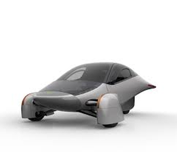
Long time ago (2014) before Tesla, et al really took off, I was thinking of building a real lightweight vehicle. Something like the Aptera coming out now. For fun... not for sale. I found this big DC motor cheap... I think something like 24 volts, 100+ amps. The motor controllers were as much as the motor and I thought I'd do it with Mosfets in parallel. I got as far as studying the vehicle dynamics and purchasing the spring/shock towers, wheels and brakes. I finally shelved the idea... imagining being next to a Chevy Suburban... then being under a Chevy Suburban. 🙄
VBR,
Inq
@inq - its funny you mention Tesla, that really makes me feel old! The last time I messed with microcontrollers, the guy that was helping me troubleshoot (my T.A.) was JB Straubel... when he was still a student!
my T.A.
As in Trans Am? I had the Z-28 equivalent. Hell of a fun car to steer with your right foot! And four wheel drifts, nice and predictable. Not that I did such irresponsible stuff on the street. 😉
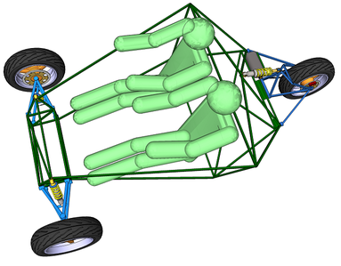
This is about as far as I got, although I was debating about putting all the batteries and dual motors to drive each front wheel and punt one in the back.
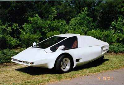
And this is surprising close to what I imagined for a body, except lower... I wanted to look barely over the wheels Formula One style.
3 lines of code = InqPortal = Complete IoT, App, Web Server w/ GUI Admin Client, WiFi Manager, Drag & Drop File Manager, OTA, Performance Metrics, Web Socket Comms, Easy App API, All running on ESP8266...
Even usable on ESP-01S - Quickest Start Guide
my T.A.
As in Trans Am? I had the Z-28 equivalent. Hell of a fun car to steer with your right foot! And four wheel drifts, nice and predictable. Not that I did such irresponsible stuff on the street. 😉
T.A.: Teaching Assistant, but I had a soft spot for the Z-28 as well, thought never had one. (wasn't "IROC" the really sup'd up one? There was a rich kid in my school who's Mom bought him one - still remember that, what a beast!!
I wouldn't do such irresponsible things either, but you know, if as a teenager, one practiced 4 wheel drifts on my parents car doing circuits in a gravel parking lot at the beach when the lot was empty in the winter, it would sure make one feel comfortable recovering from spinouts on slippery roads should that happen later in life!
Funny about the 3-wheeeled car, I bought plans for a three wheeled car from Popular mechanics when I was a kid, that looked surprisingly similar, but had the back 3/4 of a motorcycle welded on the back. Put that one out to pasture when I came to understand the drawbacks of the foam/fiberglass body in a collision!
Hi @inq and @zinder,
Picking my way around the literary embellishments ... and pointing out datasheets are written for a reason ... and simulators can be a handy way of getting some ideas straighter, with minimal impact on the spares cupboard due to magic smoke emissions .... 🙄
SERMON WARNING .... this threatens to be a 'box set' of sermons ... no responsibility for the consequences is accepted by the author.
...........
Pin connections ... datasheet is your only friend here ... they get swopped around just to keep on your toes...
Which one connects to...
In low power, low voltage circuits, then you can sometimes get away with little more than the FET itself, but as voltages and currents increase, more reading for some 'real' circuits is probably a good idea ...extra resistors, capacitors, transistors, driver chips, etc. can make all the difference!
Is it PNP, NPN
There are quite a few different basic types of transistor, the two most common are BJT (Bipolar Junction Transistor) and MOSFET (Metal oxide Silicon Field Effect Transistor). Each of these two, further split into two categories:
- BJT
- npn
- pnp
- MOSFET
- n-channel
- p-channel
So if you want to play with MOSFETs, your choices are n-channel and p-channel, not npn or pnp
Some you can not mount on a common cooling plate because of some reason, some you can?
Small (low power) devices tend not to be physically compatible with mounting plates, but they can rely on the PCB to conduct heat away. Some could have extra pads to solder down to improve the heat conduction.
Larger devices often have an exposed metal surface which is intended to be in contact with a 'cold' surface to enhance the heat removal.
As good heat conductors have a tendency to also be good electrical conductors, it is inevitable the exposed metal surface will often also be electrically connected to one of the device pins ... drain or source. Manufacturers move things around to suit their device, so the datasheet is needed for the exact details, but I am sure you can appreciate that if the metal surface is also the drain (or the source), then you must take the electrical consequences into account.
As a 'get out of jail' approach, you can put an insulating washer between the heatsink and the transistors metal surface, plus using suitable fixing, such as nylon bolt, or metal bolt with plastic sleeving. Traditionally the washers were (and still are) mica, but silicon ones are also available. To improve the thermal contact, a very thin layer of thermal paste can be used to 'wet' the metal to washer surfaces.
The disadvantage of using an insulating washer, is that it reduces the efficiency of the heat transfer, and is also an extra component to fail. If you are handling significant voltages, assume the washer will fail and that the only subsequent consequence will be a blown fuse or similar -- not an electrocuted user!
Capacitance and charge transfer
Pseudo-randomly picking an n-channel MOSFET data sheet
Headline details include: V DSS = 30V, RDS(on) max = 12mΩ I D =62A
Designed for switch mode converters. Very low Rds(on) at 4.5V Vgs
So not a 'logic level compatible' device, but a 5V logic device that achieves nearly 5V logic high into a high impedance load should be able to get a low Rds(on), once all the capacitances have reached a steady state.... so as an 'occasional' event, it may 'work' ... but the transition may take some time and even 'strain' on the logic chips output stage.
....
It should be understood the capacitance values quoted in the data sheets are approximations, as the values are voltage dependent.
With a 'simple, classical' capacitor, the amount of charge held is directly proportional to the voltage Q = CV
Q (charge in Colulombs) = C (capacitance in Farads) * V (Voltage across the capacitor in Volts)
But in the case of the capacitances, such as from gate to source, this proportionality is more complicated.
Hence, manufacturers also quote the amount of charge needed to establish a particular voltage condition.
The charges, such as Qgs (charge gate to source) of 6.7 nanoCoulombs (nC) may sound insignificant, for a Vgs of 4.5V, but assuming it is being driven with a PWM square wave from 0 to 4.5V, then this amount of charge must be supplied to go from 0V to 4.5V, and then discharged to go back to 0V, for every cycle.
To minimise the time the MOSFET is kept in the 'linear' transition, this means aiming for switching times in the nanoseconds range.
And 1 nC flowing for in a time of 1 nS (1 nanosecond), implies a current of 1A (assuming current level is the same over that 1 nS)
So it is not unusual for power MOSFETs to need driver circuits capable of delivering gate currents measured in Amps.
.......
Specifying the amount of charge to perform a voltage transition, is sometimes considered a fairer way of comparing different devices ... i.e. if one device needs 10 nC per switching operation, and another 20 nC to perform the equivalent operation, then from this aspect of their operation, the first one will be more efficient.
This is only one of the constituent power loss mechanisms to consider, but for power supplies, etc. often one of the main power loss mechanisms.
.......
Clearly, delivering this amount of current is not a trivial task ... so there are specialised chips for the job.
Quick Google suggested the following light reading (not a product recommendation .. just the first to show up ... there are many others):
List of drivers for 'low side' MOSFET driver products:
https://www.microchip.com/en-us/parametric-search.html/391
Typical device datasheet (from above list):
An Application note, also from above list:
https://ww1.microchip.com/downloads/en/Appnotes/00786a.pdf
The above sheets are not particular product recommendations, but intended to provide an illustration of the kind of devices you might consider putting between your Arduino and a 'beefy' power MOSFET.
......
Summarising:
if you ever consider building a switch mode power supply, based on a chip that drives one or more external MOSFETs, then the chip will (probably) have similar technology to the above driver chips onboard.
General purpose microcontrollers, (i.e. not those specifically designed for functions like power supplies or motor controllers, with specialised pin drivers) need extra help.
.....
---------------------------- End of Part 1 ---- Part 2 to follow --------------------
@inq et al, ... PART 2 or should that be PART DEUX?
Am I understanding correctly...
-
That if the "Gate-Source Threshold voltage" is say 2.5V, it can be fully energized by a 3.3V ESP8266.
Two possible gotchas for the price of one here .... it is a bit like the glass half full vs glass half empty situation.
- You want your switch to have a very low resistance when it is switched on ... every extra milliOhm for Rds(on) means hotter device, wasted power, etc., etc.
- You want your switch to completely isolate the bit of circuit connected to its drain from the bit of circuit connected to its source, otherwise current will 'leak' through when it is switched off with all sorts of bad consequences for the quality of your product.
In a perfect DIGITAL world, every MOSFET would be either infinite resistance or zero resistance, never somewhere in the middle. (The analog fraternity wouldn't be happy though..)
Before I have mentioned the 'dynamic' in-between which occurs during each switching operation .... now I need to look at the 'static' conditions, when the gate voltage is fixed/stable, at least for a few moments.
For the FET IRF3708's data sheet I referenced previously, one line reads:
This is saying, that when the Vgs is at a particular voltage in the range, (the actual voltage depending on the sample device, etc., ) 0.6V to 2.0V, with Vds = Vgs, then the drain-source current will be 250 microAmps.
Bearing in mind this is power device designed to carry 50+ A, 250uA is usually considered insignificant, so in this case, the threshold is saying, how near to zero V you need to drive the gate to be sure the device is effectively switched off.
The probability is that the leakage current would be lower at 0V, than at 0.6V, but you would need some sensitive gear to even measure the difference, let alone worry about it.
This is explicitly shown by another line:
.....
Elsewhere, it also says:
This shows the RDs(on) at different values of Vgs ... clearly in this range, higher Vgs means lower Rds ... but achieving higher Vgs means more charge has to be transferred every time it is switched (assuming the 'off' Vgs is chosen to be the same) and even for a static case, a higher voltage must be provided, which can be difficult for a microcontroller.
So it depends on the requirement of the application ... a 3.3V logic chip might be able to use it to switch few Amps, on an 'occasional' basis, but 10V drive will be needed to get the lowest Rds(on) for higher current applications.
As well as the 'logic compatiblity' question, even assuming the designer can achieve any Vgs 'on' (in the range say 2.8V to 10V) . If it is being switched at a high rate, there may be a 'sweet spot'. If Vgs is set too high, the increased dissipation from the gate drive may exceed the reduction in dissipation due to Rds being lower during the conduction part of the cycle.
TAKEAWAY 1 ... Threshold is a 'meaningless' word in this context .. the behaviour is continuous function ... arbitrary 'thresholds' can be defined at any point along the line ... and different people pick different points .. so ignore the word, and look for points defined by voltages and currents, and then relate them to your circuit.
TAKEAWAY 2 .. 'logic circuit compatibility' is as vague as 'threshold' ... again look at the numbers and compare them with the circuit you have to connect to.
---------------------------
There is a significant part of time while it is going from near zero resistance to near infinite resistance during which it obviously is converting a lot of electricity to heat.
I am sure you will see that statement can be true if the device is conducting a considerable current from drain to source, but also that, it is only part of the picture ....
----------------------------
That the faster the PWM frequency, the more of these periods happen, thus making it less efficient AND producing more heat.
Again, there is an element of truth in this statement, but in most cases, it is not that simple...
Such efficiency usually relates to applications like switch mode power supplies. These rely on inductors and capacitors to store and control energy. Lower frequency usually means more microFarads and more microHenries, both implying more cost, weight and volume.
Picking the 'sweet spot' is again an art ....
------------------------------
That the larger the motor, thus more current/voltage required, causes that transition to stretch out due to this capacitance and make things even worse.
You can only get less mechanical power out than electrical power you put in, and power is "Volts x Amps", so, yes increasing the power of the motor implies increasing one or both of Volts and Amps.
And increasing Volts or Amps rating of a device tends to mean more capacitance.
There are a number of different mechanical arrangements inside a power FET, but a common approach is to have a very large number of identical FETs, all connected in parallel ...
so to make a higher current model, the 'simple' manufacturing option is to do a 'copy and paste' job to have more devices in parallel....
and the effective capacitance of two or more capacitors in parallel, is the sum of their individual values.......
(I am sure it's a technically more challenging than my copy and paste description, but hopefully you get the idea.)
-------------------------
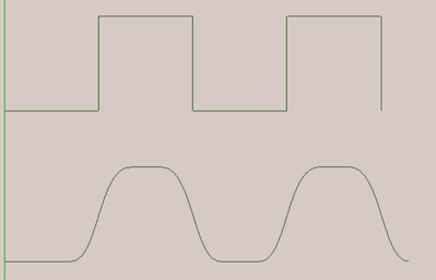
So the theoretical and the reality are more like:
The scope traces I have seen look more like a rugged mountain ranges, with overshoots, glitchy bits, etc., but yes the slopey transitions give the right impression of the problem.
But if you actually use a scope on a switch mode power supply, and the trace looks like your diagram, then your scope is missing about 95% of the fine detail .... perhaps you have it switched to a bandwidth limited mode! MOSFETs can achieve very fast switches, and affording a scope that can capture it accurately is extremely hazardous to the payment card.
-------------------------
And because the ESP8266 miniscule pin current, it takes even longer... wasting more power?
Same story ... so potentially yes ... but you have to do the sums ... one person's leakage current is another person's power supply .... and as Richard Feynham famously said ... there's plenty of room at the bottom.... it all depends on your application.
-------------------------------------------
. I think something like 24 volts, 100+ amps.
That is 24 * 100 = 2400 W = 2.4 kW ... just over 3 horse power, assuming 100% efficiency.
I couldn't find a motor power for the Aptera ... but a Renault Zoe, small, 3-door hatchback is 100 kW motor (135 horse power) ... so I might wildly guess the Aptera will be around 50 kW or more to provide 'acceptable' performance.
And your vehicle would have about the same power as a modest petrol/gas 'manual push along' lawn mower. 🤨
More seriously, you can see the power levels even 'everyday, production' cars need to handle.
There is a kind of 'two transistor hybrid' device, called an IGBT which is often employed as a higher power upgrade for MOSFETs, but the boundary is 'soft' , with MOSFET's getting more powerful .. I have never played with one.
https://toshiba.semicon-storage.com/eu/semiconductor/knowledge/faq/mosfet_igbt/igbt-001.html
came up from Google, if you fancy a break from my waffle.
------------------
p-channel versus n-channel
Much of the above applies to both. To my limited grey cell, there are two points to consider at this level:
- Am I switching 'high side' or 'low side'?
- P-channel devices have higher Rds (on), all else being 'equal'
If you consider the common case of a single supply, say a battery, and a load, say a low power/voltage light, with a MOSFET switch to turn the light on and off ... and we want the MOSFET gate drive to be a simple connection to an Arduino GPIO pin. (The battery also powers the Arduino)
So the negative battery terminal will be the '0V' line.
The simplest circuit would insert an n-channel MOSFET between the 0V line and the light ... thus the MOSFET source would be at 0V, the light connected to the drain, and Arduino GPIO connected to the gate. The Arduino could turn the light on, by setting the GPIO to high (3-5V) and off, by setting it to low (near 0V). This will work fine, providing we keep within device specs, etc.
This arrangement is known as low side switching.
Of course, this means the light connection, NOT connected to the drain of the MOSFET is connected to the positive battery terminal and is thus 'always live'. This means the circuit cannot be automatiacally 'depowered', as we might wish to do in the event of a fault or for some other safety reason.
To do this, we need a 'high side' switch, which interrupts the connection between the positive battery terminal and the light.
In principle we could wire our n-channel MOSFET into that position. Now to turn the light off, we need to construct a circuit that effectively linked the gate to the source .... this is a bit more complicated than a straight wire from the Arduino, but not that hard, as the voltage of both pins stays in the range supplied by the battery.
The tricky bit is when we want to switch the power on ... then we want the MOSFET to effectively connect the drain to the source, so that the drain voltage is (very nearly) the same voltage as the source, which is itself connected to the battery positive terminal. But to do this we need to drive the gate of the MOSFET some 3-5V positive of the source voltage.
Unfortunately, we do not have any positive voltage greater than coming from the positive terminal .. we wold have to make a DC-to-DC power supply to generate this new voltage .. feasible of course, but very inconvenient.
At this point, the p-channel device looks much more attractive ... it is 'backwards' compared to n-channel, and only needs voltages in the range zero to battery positive terminal ... it is still more complicated than the low side switch, but much easier then the n-channel case of high side switching.
------------------
And the downside of using p-channel .... intrinsically, p-channel devices have a higher Rds(on) than their equivalent n-channel cousin. For low power cases, this may be a trivial problem to solve ... buy the 'next size up' device to compensate. However, as the power to be transferred increases, this 'solution' becomes more impractical, and going for the more complex n-channel approach becomes more desirable and even essential. Very low RDs(on) p-channel devices do not exist.
...............
And this is the end of Part Deux ... I hope it is of some interest.
Best wishes, Dave
It physically worked, but produced significant heat. It also ran them slower than direct wiring even though the PWM was set at 100% duty cycle. The fact that when I then tried these drivers meant for the job seemed to do no better and could cook eggs, left me thinking I was close.
I think your posts convince me just enough... that I don't need to be trying to design high powered motor drivers. And I'll simply take this as a postulate.
Picking the 'sweet spot' is again an art ....
VBR,
Inq
3 lines of code = InqPortal = Complete IoT, App, Web Server w/ GUI Admin Client, WiFi Manager, Drag & Drop File Manager, OTA, Performance Metrics, Web Socket Comms, Easy App API, All running on ESP8266...
Even usable on ESP-01S - Quickest Start Guide
Hi @inq,
I hope the two part sermon wasn't too daunting, but gave a little insight into what to look for.
There is nothing wrong with the 'trial and error' approach, providing it does not involve safety or other unacceptable risks - we all learn more from the things that fail than from the successes ... providing we survive the failures! And if you get a failure, then I hope the stuff I presented gives an indication of what to look for and how to fix it.
Please feel free to query any bits I have muddled, got wrong or whatever.
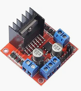
When there is a 'Commercial Off The Shelf' device, as a board or a chip, that has been designed to do a job, then inevitably thought will have been expended in designing and building the device .... to replicate the device, especially without directly copying it, implies a similar level of commitment. So it seems perfectly logical to make use of any convenient COTS building blocks, and save your creative talents and time for the bits that are not readily available in COTS form.
For the block in your illustration, the presence of a multi-legged chip suggests that most of the intellectual thought will have occured in the chip design house .. and they will often have written app notes and data sheets. The tricky bit (at present) can be buying a small quantity of the chip, and at what price. Many of the boards currently available through the bazaars are at prices below that of the principal chip on the board through the main distributors. Of course, this implies some 'short cuts' have been made somewhere, so consider the possible risks and benefits.
Best wishes, Dave
I hope the two part sermon wasn't too daunting, but gave a little insight into what to look for.
I found it perfect, but it was early, the house was quite and I could actually think about it. 😆 As, I mentioned... the SparkFun, Adafruit variety with one picture, and a single paragraph will convince you ANYONE can do this. They don't even mention... don't try this at home kiddies with 5+ kW motor.
I did notice in the datasheets that the N-channel did seem to be more efficient... and didn't even think to realized the down-side thing still had power on it! $#!+ NOW! A 1000 amp capable LiFePO4 battery (isn't that large) will melt wrenches Jiffy Quick. Ask me how I know? 🙄
I get a little complacent (maybe cocky) when I can build a smart light / gizmo for $4 that I can program to my hearts content and not have to have it go through some company's web servers to control it.
Please feel free to query any bits I have muddled, got wrong or whatever.
Thank you for the offer and I certainly will ping you if I ever grow big brass ones needing multi-kilo-watts. You've convinced me that I can't create a safe AND efficient ESC for the price of one like @headingholder found... unlike a smart bulb. I guess... you've even made me leery of a cheap Chinese knock-off that had no UL/CE listings. And even if it did... a silk-screen is easy to produce. Buyer beware.
3 lines of code = InqPortal = Complete IoT, App, Web Server w/ GUI Admin Client, WiFi Manager, Drag & Drop File Manager, OTA, Performance Metrics, Web Socket Comms, Easy App API, All running on ESP8266...
Even usable on ESP-01S - Quickest Start Guide
Hi @inq,
Good to hear that you found it interesting. I must admit I was only considering relatively low power systems ... I am very much aware that even low voltage systems can have a ferocious bite when they have a low impedance source, plus the risks of fires, toxic fumes and explosions from batteries when maltreated.
Higher voltage systems present more obvious hazards, but the odd addage is probably still relevant:
The Volts Jolts, but it's the Mils that Kills (Mils referring to milliamps, of course)
The Residual Current Detectors (trips) that are commonly used in domestic mains power systems usually trip at just under 30 milliAmps, for just under 30 milliseconds, on the basis that this is though to be the 'threshold' that electric shocks are more likely to be fatal. Wet areas, such as near swimming pools, often adopt a much lower current limit like 6mA.
To the best of my knowledge, there is only scanty research to demonstrate this threshold is the most appropriate one for humans .... allegedly, it is difficult to recruit enough volunteers willing to prove the point 🤔 However, fatalities are reported to have occurred with current levels below 30 mA, so treat this like a safety belt ... wearing a safety belt improves your chances of surviving a serious crash .... but not being involved in the crash always has a much better predicted prognosis.
-------
Sounds like you were lucky you only lost a wrench ... people have been killed by the explosion of lead-acid car battery when shorted with a metal tool .. and the lithium based equivalent batteries have a much more lethal arsenal of nasty tricks to show their displeasure.
Personally, I have always tried to keep my distance from higher power stuff ... but I am not the adventurous or brave type. Whilst I buy stuff from the usual bazaars, I would be very cautious about any equipment handling higher voltages or currents. The general level of construction, etc. can be very poor.
---------
At your own risk of course, experimenting with FETs on lower power systems can be rewarding, but even with just an 18650 or similar power source, try to ensure you have at least one, preferably two fail-safe mechanisms to cut the power when something goes wrong ... and a quick exit route if something decides to start smoking ... e.g. lithium-ion cells can produce a lethal cocktail of gases, including carbon monoxide, when they overheat.
Have fun, but stay safe, Dave

