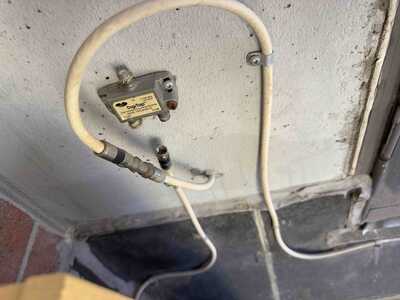
It's a little project after all... 😉
Few years ago, the tech from my internet provider put this splitter outside my house. I no longer need the cable going in the baseman. So at least, i have to put a dummy load ( 75 ohms i think or 50 ohms ? ) to get ride of the coax cable.
The tech told me also that this splitter reduce the signal to correct a random connection problem ( something like once a month ). By putting the dummy load, will it change the state of the connection ?
thanks,
@solusseeke Maybe my memory is failing, but as far as I know, if you no longer need one of the splitter outputs, then just disconnect it, no dummy load is needed. What may be needed is a weatherproof cap if it is exposed to the elements, though.
First computer 1959. Retired from my own computer company 2004.
Hardware - Expert in 1401, and 360, fairly knowledge in PC plus numerous MPU's and MCU's
Major Languages - Machine language, 360 Macro Assembler, Intel Assembler, PL/I and PL1, Pascal, Basic, C plus numerous job control and scripting languages.
Sure you can learn to be a programmer, it will take the same amount of time for me to learn to be a Doctor.
Hi @solusseeke,
NB my answers are based on general behaviour of transmitting data ... I don't know about any 'special' problems that may be common with Internet provider's equipment, etc.
It's data sheet is on the web https://www.antronix.com/datasheet?id=ds-1064-ss_cmcdt2100.pdf
First glance suggests it is 75 Ohm, but please check for yourself.
The general answer to your question is that the signals seen at each of the three connections are all affected by what is connected to the other two connections. However, IF it was correctly terminated when it was connected to the basement, and you replace it with the correct (ie equivalent) dummy load, then all should be well, as the effect of the loads should be equivalent.
Late PS> I note Ron (@zander) has said you can leave it open-circuit. In reality, this may be true, as the reflections in your particular case may not cause a problem. It is not uncommon for electronics to be sufficiently resilient to carry on working in the presence of a 'fault'. I still recommend using the dummy load, but accept it may not appear to make any difference. Predicting the effect of stray reflections, particularly without being familiar with the exact circumstances, products, etc., is not realistic.
However, I am concerned about your comment about attenuation fixing random connection problems. Anything is possible if the signal strength and quality are not within the specified limits, but diagnosing whether you are really fixing such fundamental problems, (instead of just altering it enough to get by for another day) tends to require some expensive test gear and specialist knowledge. I don't know your tech, but I am a cynic.
Good luck, Dave
@davee @solusseeke I just remembered I have one of those devices as well so took a picture which is attached. Since you now have only 1 input and 1 output, just connect them together like mine is.
First computer 1959. Retired from my own computer company 2004.
Hardware - Expert in 1401, and 360, fairly knowledge in PC plus numerous MPU's and MCU's
Major Languages - Machine language, 360 Macro Assembler, Intel Assembler, PL/I and PL1, Pascal, Basic, C plus numerous job control and scripting languages.
Sure you can learn to be a programmer, it will take the same amount of time for me to learn to be a Doctor.
Hi Ron @zander & @solusseeke,
Thanks Ron for posting a useful picture.
I half wrote a similar answer to the one Ron is showing, albeit it only said find a 'back-to-back' connector, as I wan't sure what type the connectors were, whilst Ron has shown a more useful photo.
The only reason I changed my mind was the 1st post included:
The tech told me also that this splitter reduce the signal to correct a random connection problem ( something like once a month ).
I already shared my concern about this diagnosis .. and that is still valid ... however if the signal is too strong, and of course I don't know if that is true or false, then this suggests an attenuator is also required.
From the first glance at the data sheet, I got the impression, that the tapped signal will be attenuated by 6dB, compared to the input, so this might be a guide as to the level of attenuation provided by splitter ... it seems like a reasonable starting value.
Sorry, I am adding more doubts than answers, but without 'hard data', the best I can do is to suggest options to try.
Best wishes and good luck, Dave
@davee I will bet a coffee the tech was blowing smoke.
First computer 1959. Retired from my own computer company 2004.
Hardware - Expert in 1401, and 360, fairly knowledge in PC plus numerous MPU's and MCU's
Major Languages - Machine language, 360 Macro Assembler, Intel Assembler, PL/I and PL1, Pascal, Basic, C plus numerous job control and scripting languages.
Sure you can learn to be a programmer, it will take the same amount of time for me to learn to be a Doctor.
@davee With your help and the one from Ron i could now distinguish a way.
According to the specs of the splitter, i understand that the 6db filter is only applied to the "tap entry" and not to the "output entry". I'm right, isn't it ?
The "tap entry" was the connection to the coaxial cable going to the basemen. So, i no longer need the splitter itself if i remove the "TAP" coaxial . I will use a union to connect the former coaxial "IN" and "OUT".
So luck have nothing to do, when helping hands are ressourceful ! 😀
Thanks gentlemenS !
Sylvain
Hi @solusseeke,
The splitter is so named because that is what it does ... some power to one port, some power goes to the other port, and some 'gets lost' in the middle. Of course, energy cannot be created or destroyed, so by 'gets lost', it is actually converted to heat, but the levels are so small you would need some amazing equipment to detect the heat.
So if it works, great carry on, job done. As Ron (@zander) mentioned, make sure water cannot corrode it.
If you start getting new problems, then you may need to do some backtracking.
Good luck ... hopefully all will be well ... Dave
@davee @solusseeke I think it's full name is 'Unpowered splitter'. There is a powered variant for splitting off more than 2 or 3 devices or longer distances. Here is one by the same company LINK
First computer 1959. Retired from my own computer company 2004.
Hardware - Expert in 1401, and 360, fairly knowledge in PC plus numerous MPU's and MCU's
Major Languages - Machine language, 360 Macro Assembler, Intel Assembler, PL/I and PL1, Pascal, Basic, C plus numerous job control and scripting languages.
Sure you can learn to be a programmer, it will take the same amount of time for me to learn to be a Doctor.


