Hello all,
After watching the video on object detection using esp32cam. I decided to try it out. I have trained the model and followed the steps as on the video. The issue comes when I try to upload the code to my esp32cam, I get brown out detector triggered over and over.
My purpose for this post if to ask of there is something I'm doing wrong and how to fix it.
This is probably the most common ESP32 uploading problem; in fact, it can be caused by many different issues. The most common one, especially with the ESP32 CAM board, is too low a voltage on the 5-volt power supply.
The condition occurs when the radio in the ESP32 is started; it takes a brief burst of current before it settles down.
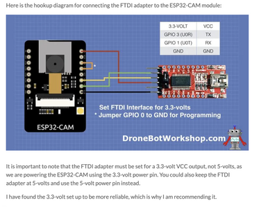
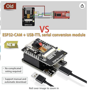
How are you using your ESP32 CAM board? Are you using an FTDI adapter, or do you have one of those ESP32 CAM carrier boards? If it's the FTDI adapter, are you using the 3.3 or 5-volt setting (5-volt seems to work better in my experience)?
You can also disable the brownout detector, although that's pretty extreme.
I find that the Espressif ESP-EYE board works much better and rarely suffers from this. If you don't need the GPIO pins, I'd recommend using that instead.
Provide a bit more info about your setup, and we can take it from there.
😎
Bill
"Never trust a computer you can’t throw out a window." — Steve Wozniak
- @dronebot-workshop I am using the 5V in the cp2102 adapter. I chose AI Thinker's esp32cam because I need the GPIO pins for micro servo control. The servos are connected on pin 14 and 15 and powered directly from the supply.
Am I misreading this, or are you sharing the same 5-volt supply with the servos and the ESP32? If so, have you tried disconnecting the servos (or at least the power lead) and then uploading?The servos are connected on pin 14 and 15 and powered directly from the supply.
Personally, I always use a separate 6-volt supply (servos work better at 6-volt than 5-volts) for the servos, as I always avoid having a motor share the same power supply as a microcontroller. Motors take large bursts of current and put a lot of electrical noise on the power supply lines.
😎
Bill
"Never trust a computer you can’t throw out a window." — Steve Wozniak
I had the same problem with the ESP32 cam module, as the 5V supply I was feeding it wasn't stable. Once I gave it a stable 5V feed, it was fine. Make sure your supply to the cam module is stable and can maintain a steady 5V with the required current draw.
I was sharing the same 5v but from the supply not powering directly using the esp32. Thanks for the reply, I will use a 6v power supply.
Also the brownout detector trigger seems to have fixed itself by switching to a different cp2102 adapter, but I'm curious about that problem and how it gets triggered and I hope to learn from your channel about the different errors we can encounter.
Thanks Bill and the entire community.
@yurkshirelad Thanks for this, I'll make sure to have a regulated supply.
Just to be clear, the 6-volts is ONLY for the servo motor! The ESP32 CAM still requires 5 volts; you would kill it with 6 volts.Thanks for the reply, I will use a 6v power supply.
Glad you have it working. If you have a multimeter, try measuring the voltage right on the ESP32 CAM module and see if changing the adapter makes a voltage difference.
😎
Bill
"Never trust a computer you can’t throw out a window." — Steve Wozniak
@madfury I have never used an FTDI, all my boards including the ESP32 have USB plugs but my understanding is there is usually a jumper on the FTDI to select either 3.3V or 5V. If you have 3.3V selected it may be the problem.
EDIT: I am enclosing Bills instructions, it looks like the CP2102 is only 3.3V.
First computer 1959. Retired from my own computer company 2004.
Hardware - Expert in 1401, and 360, fairly knowledge in PC plus numerous MPU's and MCU's
Major Languages - Machine language, 360 Macro Assembler, Intel Assembler, PL/I and PL1, Pascal, Basic, C plus numerous job control and scripting languages.
Sure you can learn to be a programmer, it will take the same amount of time for me to learn to be a Doctor.
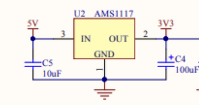
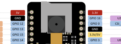
@madfury You may have already seen all this, but just in case. Here are some screen grabs from the RandomNerdsTutorial site. Many esp32 folks started their education on esp boards at this site. The first picture shows the 5V and 3.3V INPUT pins, if you use 5V the AMS1117 voltage regulator converts it to 3.3V. The board is a 3.3V board. The second pic shows where those power IN pins are, there is a power out on the right below the GND, it's output voltage is solder pad selectable. I have never found a good use for it yet. The last picture is the Nerds opinion re power, and they recommend using the 5V pin for board power.
Since I discovered the MB version of the ESP32-CAM I never have to worry about this again, it's powered by the USB connection. I even make up USB2.0 power only cables and plugs that connect to a buck converter to step down 12V (or any other voltage between 6 and 12) to the USB 5VDC. The reason for 12V is I was living in an RV so used the battery power (I had 7,200Watts of power)
In the future, I think I will switch to 18650 LiFePO4 1200mAh 3.3V. I can use 2 in series to get 6.6V and then use a buck converter to step that down to 5.1VDC. Cost in Canada is $4.25 each cell.
First computer 1959. Retired from my own computer company 2004.
Hardware - Expert in 1401, and 360, fairly knowledge in PC plus numerous MPU's and MCU's
Major Languages - Machine language, 360 Macro Assembler, Intel Assembler, PL/I and PL1, Pascal, Basic, C plus numerous job control and scripting languages.
Sure you can learn to be a programmer, it will take the same amount of time for me to learn to be a Doctor.


