The KA75330 is a voltage monitor, when an input pin drops below 3.3V the output pin goes LOW. I am trying to find a version that works like that for 5V input. Any ideas?
EDIT: I think I found one, the HT7050A-1
First computer 1959. Retired from my own computer company 2004.
Hardware - Expert in 1401, and 360, fairly knowledge in PC plus numerous MPU's and MCU's
Major Languages - Machine language, 360 Macro Assembler, Intel Assembler, PL/I and PL1, Pascal, Basic, C plus numerous job control and scripting languages.
Sure you can learn to be a programmer, it will take the same amount of time for me to learn to be a Doctor.
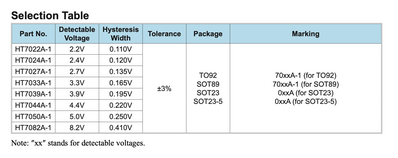
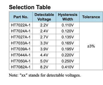
The first picture is of the various model/part numbers (detectable voltage). I chose the 5V version.
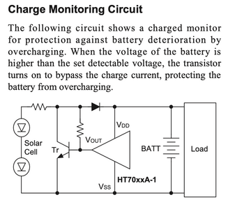
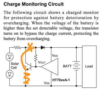
The 2nd pic is of a battery overcharge protection circuit. What I want is the reverse (kind of). I want the HT7050A-1 to turn off the battery when it falls below 5V.
OR I want the transistor to turn ON at 5V and above.
Bonus question: How do I determine values of the two resistors, and which diode is the right one?
First computer 1959. Retired from my own computer company 2004.
Hardware - Expert in 1401, and 360, fairly knowledge in PC plus numerous MPU's and MCU's
Major Languages - Machine language, 360 Macro Assembler, Intel Assembler, PL/I and PL1, Pascal, Basic, C plus numerous job control and scripting languages.
Sure you can learn to be a programmer, it will take the same amount of time for me to learn to be a Doctor.
Hi Ron @zander,
The chip is apparently designed to act as a voltage detector, which is fine. At first glance, the suggested circuit of dumping current through a load resistor, so that the effective source voltage is forced lower, has, a bit of an April Fool feeling!
However, I assume the author must have been considering low power levels, such as milliWatts, where the simplicity of the circuit might be attractive, and the usual challenges of heat dissipation, etc. are trivial to deal with.
For higher power levels, I would expect the protective/controlling circuit to include a switching element in series with the solar cell and the battery, that would open when the battery reaches the 'charged' voltage.
--------
For the low power scenario:
To specify the resistor and diode, then the actual operating conditions and components need to be considered.
The diode should comfortably be able to pass the maximum charging current, and withstand the battery voltage in the reverse direction.
The output of the chip is open drain, so the resistor should be chosen to provide sufficient base current to saturate the transistor, when the chip output goes high impedance. This depends upon the expected voltages and the gain of the transistor.
When the transistor is turned on, the resistor connected to the solar cell, forms the main solar cell load,
i.e The solar cell voltage, less the saturation voltage (of perhaps 0.3V) of the transistor, appears across the resistor, with the aim of dropping the voltage presented to the "diode plus battery", to be below the voltage needed to forward bias the diode, thereby stopping any further charge reaching the battery.
Hence, the resistor should be chosen using Ohm's law, to give a suitable voltage drop, and be capable of dissipating any heat generated, remembering that there must be sufficient voltage to keep the transistor saturated with the chosen base resistor.
-----------
Best wishes, Dave
@davee Thanks Dave, I think I can figure that out.
First computer 1959. Retired from my own computer company 2004.
Hardware - Expert in 1401, and 360, fairly knowledge in PC plus numerous MPU's and MCU's
Major Languages - Machine language, 360 Macro Assembler, Intel Assembler, PL/I and PL1, Pascal, Basic, C plus numerous job control and scripting languages.
Sure you can learn to be a programmer, it will take the same amount of time for me to learn to be a Doctor.
The first picture is of the various model/part numbers (detectable voltage). I chose the 5V version.
I want the HT7050A-1 to turn off the battery when it falls below 5V.
OR I want the transistor to turn ON at 5V and above.
Bonus question: How do I determine values of the two resistors, and which diode is the right one?
If you have an LM393 and an IRF520N lying around, here's an alternative you may find useful. The first video just shows the setup and the LM393 turning an LED on/off based on. voltage threshold. The second video explains how to insert the N-Channel MOSFET to control (turn on/off) the load.
It may not suit your purpose, but it's an interesting and useful pair of circuits that may be handy for others.
Edit: I suppose it would help if I included the URLs for the videos ...
1)
2)
Anything seems possible when you don't know what you're talking about.
@will Interesting way to do it, but costly. The LM393 is $30 for a pair but a lot cheaper on Aliexpress, 20 for $3.79 delivered. The cheapest I can mail a parcel is $20 I think, how do they do it?
Meanwhile I also have the other devices on the way, both 5V and 3.3V (I think)
I have a few IRF520, they are my goto 5V switch.
First computer 1959. Retired from my own computer company 2004.
Hardware - Expert in 1401, and 360, fairly knowledge in PC plus numerous MPU's and MCU's
Major Languages - Machine language, 360 Macro Assembler, Intel Assembler, PL/I and PL1, Pascal, Basic, C plus numerous job control and scripting languages.
Sure you can learn to be a programmer, it will take the same amount of time for me to learn to be a Doctor.
@will Interesting way to do it, but costly. The LM393 is $30 for a pair but a lot cheaper on Aliexpress, 20 for $3.79 delivered. The cheapest I can mail a parcel is $20 I think, how do they do it?
That's interesting, Amazon has them for lot less than $30/pair ...
Note that the blurb says price is for 10 of them but the inset says the unit price is $5.75 per item ?
Anything seems possible when you don't know what you're talking about.
@will You got a better search result than me, but it's still a lot more than 20 for $3.79. I don't plan on using the two devices for the 5V circuit, I already have a tiny transistor sized device coming and the main reason it is more attractive is the BIG difference in size. I want to keep the game camera as small as possible.
That's weird, now I don't see the $30 item at all after I typed lm393 in the search bar. I think I just had some sort of seniour moment.
First computer 1959. Retired from my own computer company 2004.
Hardware - Expert in 1401, and 360, fairly knowledge in PC plus numerous MPU's and MCU's
Major Languages - Machine language, 360 Macro Assembler, Intel Assembler, PL/I and PL1, Pascal, Basic, C plus numerous job control and scripting languages.
Sure you can learn to be a programmer, it will take the same amount of time for me to learn to be a Doctor.
I'm not convinced that it's a good match for your needs anyway, since he's starting at 10V. When adapted for a 5V supply, that may not leave enough voltage to drive the LM393 properly.
The only advantage of Amazon is the speed of delivery time, two days versus a month 🙂
Anything seems possible when you don't know what you're talking about.
@will Just some FYI, delivery time is 19 days, if late I get $1. If longer than 35 days I get for free. If lost or damaged I get full refund.
I just today complained about the price of something and got a full refund and was allowed to keep the device. That was a $56.31 device. It was ordered thru Amazon, but openly displayed as coming from China and that probably means Aliexpress.
The HUGE problem though (now that I watched part of the video) is the need for a reference voltage. I will not have that, the other device I ordered somehow magically knows what 5V is??? The devices come in various voltages (see pic)
First computer 1959. Retired from my own computer company 2004.
Hardware - Expert in 1401, and 360, fairly knowledge in PC plus numerous MPU's and MCU's
Major Languages - Machine language, 360 Macro Assembler, Intel Assembler, PL/I and PL1, Pascal, Basic, C plus numerous job control and scripting languages.
Sure you can learn to be a programmer, it will take the same amount of time for me to learn to be a Doctor.
The HUGE problem though (now that I watched part of the video) is the need for a reference voltage. I will not have that, the other device I ordered somehow magically knows what 5V is??? The devices come in various voltages (see pic)
In the video he just used a voltage divider to split the incoming voltage in half.
Anything seems possible when you don't know what you're talking about.
@will Yes, but that is NOT a constant 5V, as the voltage drops below what I want the split voltage that is also the REF also drops so the circuit never trips.
Interesting device and I do thank you for pointing it out, I like learning new things sometimes, but it does not do what I need. The HT7050A-1 does. It somehow (internal zener?) knows what 5V ?feels? like and needs only VCC, G, and an output pin to act as the signal to me to do something.
First computer 1959. Retired from my own computer company 2004.
Hardware - Expert in 1401, and 360, fairly knowledge in PC plus numerous MPU's and MCU's
Major Languages - Machine language, 360 Macro Assembler, Intel Assembler, PL/I and PL1, Pascal, Basic, C plus numerous job control and scripting languages.
Sure you can learn to be a programmer, it will take the same amount of time for me to learn to be a Doctor.
but it does not do what I need. The HT7050A-1 does. It somehow (internal zener?) knows what 5V ?feels? like and needs only VCC, G, and an output pin to act as the signal to me to do something.
Yes, it looks like each item in the line is keyed to a specific maximum voltage and just returns a value [0-1023) depending on the input voltage sent to it. Doesn't look like it can recognize anything larger than the voltage specific to that model.
I wonder how tolerant it is, I mean if you hook it up to a USB device supplying it with 5.2 V, does it give values from 5.2V to 0 or just from 5.0V to zero ? Similarly if you hook up a Li battery will it actually show the battery voltage as a fraction of 5V ?
Anything seems possible when you don't know what you're talking about.
@will Maybe you missed the post where I used their application note to do what I want with a minor change. See attached file.
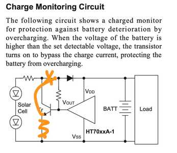
Delete the solar cell, move the battery to where the solar cell was. Now the transistor will be ON as long as the battery voltage is 5V and above.
I just now realized this isn't what I want, but these are the kinds of devices that will enable what I want. I am overwhelmed with too much new info and I need to slow down and draw out what I want then I can build it.
Oh well, more spare parts on their way.
First computer 1959. Retired from my own computer company 2004.
Hardware - Expert in 1401, and 360, fairly knowledge in PC plus numerous MPU's and MCU's
Major Languages - Machine language, 360 Macro Assembler, Intel Assembler, PL/I and PL1, Pascal, Basic, C plus numerous job control and scripting languages.
Sure you can learn to be a programmer, it will take the same amount of time for me to learn to be a Doctor.

