Ron Bentley
Creativity is an input to innovation and change is the output from innovation. Braden Kelley
A computer is a machine for constructing mappings from input to output. Michael Kirby
Through great input you get great output. RZA
Gauss is great but Euler rocks!!
Hi @ronbentley1,
I am aware these shift registers are quite popular and I think a number of forum users will find your explanation extremely helpful.
Reading your text, a couple of points came to mind:
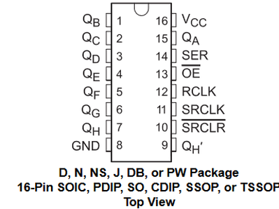
Your pinout diagram is slightly misleading ... For comparison, I have copied the Texas Instrument datasheet one
( for the full datasheet see: https://www.ti.com/lit/ds/symlink/sn74hc595.pdf )
You may notice Pin 13 has a bar over 'OE' and Pin 10 has a bar over 'SRCLR'.
The bar is equivalent to 'NOT' ... that is to make the pin action 'happen', you take the pin Low (0V).
(Sorry, I haven't figured out how to show the bar in this text ... I'll write '(not)SRCLR' a reminder of the bar. )
For example, as you eloquently explain and demonstrate, taking the (not)SRCLR clears the shift register ... for 'usual operation', this pin is held high.
Correspondingly, your mystery pin 13 'OE' stands for Output Enable. It is 'usually' held low, to enable the Outputs Qa...Qh, so that they can output High or Low, according to the value held in the internal latch.
Taking (not)OE pin 13 high, disables those outputs to a 'high impedance' state (AKA tri-state).
In your circuit diagram, pin 13 is connected to the Arduino ground pin, and hence the Qx outputs are always enabled.
--------
As an aside, you say that:
I now knew why the original code didn’t work – it did half a job, it did clear the shift register but, without the latch cycle, it did not update the storage/latch register so I could not witness the operation.
This suggests a reason why pin 10 might be labled "(not)SRCLR", instead of "(not)MR".
"MR" (Master Reset) might be interpreted as the pin that resets the whole chip .... but as you thoughtfully explain, the outputs do not change until you update the latches.
Hope this is of interest and helpful. Best wishes, Dave
Hi Dave
many thanks for your post and observations.
Interesting - the image of the 74HC595 pin outs in my post do not show the bar symbol over OE and SRCLR as you have noted. Strange, as my Arduino Project Hub article on this (see link in my post above) does indeed show these bars!
I can only assume I picked up an incomplete image for the IC from somewhere when I put the post together, don't know where, but I will be alert to check for completeness in future.
If you see my Project Hub post you will see that I came to the conclusion that programmatic control of the SRCLR pin is of dubious value and I would, perhaps, prefer to have the digital pin back for other uses.
As for the OE pin then I would again struggle to see a programmatic use for this pin also.
I hope my post extends the understanding of interested parties in using these very useful ICs and thank you for noting the error in the 74HC595 image and your explanation of the OE pin functionality.
Ron Bentley
Creativity is an input to innovation and change is the output from innovation. Braden Kelley
A computer is a machine for constructing mappings from input to output. Michael Kirby
Through great input you get great output. RZA
Gauss is great but Euler rocks!!
Hi @ronbentley1,
Thanks for taking the trouble to prepareyour explanationa and of replying to my comments.
I thought it was strange that your image had lost its overbars as well ... just an everyday hazard of the Internet where copying something is a trivial operation.
I guess the 595 was designed in a different era, before the proliferation of low cost microcontrollers, when it would have been part of main controlling mechanism in its own right, and clearing the shift register might have been a useful function.
Similarly, the OE output enable is presumably to allow two or more 595s to have their outputs paralleled in tri-state bus fashion, with the OE of each being used to select which device is driving the bus at any one time.
Given that the Texas Instrument 74 series dates back to around 1970, it seems remarkable (to me) that the same functions, albeit in CMOS technology, are still around, even if they are limited to playing a support role, with some of their functionality being 'a solution looking for a problem'.
Best wishes, Dave
Thanks for feedback.
I had similar thoughts about the age of the design.
I like your observation about the use of the OE pin, I will have to give that a bit of thought about how useful it may be (or not).
Cheers for now
Ron Bentley
Creativity is an input to innovation and change is the output from innovation. Braden Kelley
A computer is a machine for constructing mappings from input to output. Michael Kirby
Through great input you get great output. RZA
Gauss is great but Euler rocks!!

