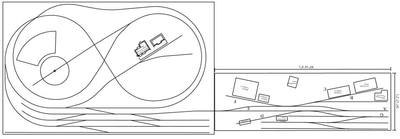
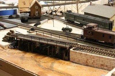
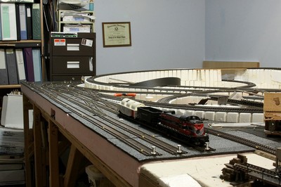
The following photos and video are of Photo Bud's HO scale model railroad.
Schematic of Layout
Coal Yard
Partial Layout view
Video
DroneBot Workshop Robotics Engineer
James
This information was originally posted in my introduction thread and Robo Pi kindly suggested that the links posted in it should have been embedded in a thread and placed here for those who are using Arduino/RPi in model railroading which I have been exploring. One of my first sketches is for sequenced lighting in an HO model railroad building. Although never implemented, the sketch was successful and I will post it the near future.
Enjoy, and please let us see what you are up to, both in model railroading and the microprocessing world.
Photo Bud (aka John)
The Old Curmudgeon!
That's a beautiful layout you have there John. And I know that represents a whale of a lot of work to get it to the stage you currently have it. It looks like you might be approaching the stage where you can start focusing on the dioramas. You did a wonderful job with the coal yard. If you keep that kind of work up you're going to have a totally awesome layout as you continue to landscape it.
With the Arduino you can not only automate the trains and turnouts, etc., but you can also use Arduino to animate diorama effects. I've see them used to flicker different shades of red, orange, yellow and white LEDs to simulate campfires etc. It can make a very realistic looking campfire, or coal furnace, etc.
Another trick I saw was to use a bright white or bluish LED that flickers as a welder appears to be welding. And of course by using servos you can animate all manner of motion. The possibilities are endless.
By all means keep us updated on your MRR projects. I would like to see any diorama work you do animated or not. Dioramas have always fascinated me. Also if you do any detailing on your rolling stock that's always cool to see too. Thanks for sharing your MRR with us.
DroneBot Workshop Robotics Engineer
James
Photo Bud (aka John)
The Old Curmudgeon!
Note that above use of color LEDs was to ensure the code was acting correctly, not to reflect what would actually be used in a structures.
Photo Bud (aka John)
The Old Curmudgeon!
You could use that single Nano to drive the lights in several buildings at once. All you would need to do is drive several LEDs in parallel. Each LED being in a different building. So you could run a whole neighborhood off one Nano, without the need to use anymore I/O pins. You might need to drive the multiple LEDs through an opto-isolator chip though so you can run them off a separate power supply.
You can also use the 74H595 Shift Register to drive as many LEDs as you like using only 3 pins of the Nano.
See this thread: Control 12 leds from arduino
We were just discussing how to use shift registers to drive multiple LEDs.
DroneBot Workshop Robotics Engineer
James
Wow, what a great idea, loved the video and it really makes sense!
Photo Bud (aka John)
The Old Curmudgeon!
John, I was thinking about your application here and realized that for your MRR layout the shift registers would work extremely well. And here's why,...
Let's say that on one section of your layout you have a little collection of various structures. Say maybe 5 or 6 of them. And you'd like to animate various things inside each building or structure. What you could do is mount just a single 74H595 chip in each of these buildings or structures. And then you'd have 8 outputs available for that particular structure. You don't need to use all 8 of them, just use whatever you need for that diorama effect.
Then you only need one Arduino to control all of these buildings or structures in that neighborhood of the layout. And more importantly you only need to run 3 wires from the Arduino to the first building. Since they are cascaded there will only be 3 wires running from the Arduino to the first building, then three wires running from that building to the next building, and so on.
So with a run of only 3 wires going around the whole neighborhood you'd be able control a whole bunch of effects in all these different buildings or structures. This would reduce the amount of wiring for the layout in general. The more complex wiring would only be contained within each of the buildings/structures.
I hope what I just said makes sense. If not, I can draw up a graphic to better explain it. This would really cut down on the amount of wires you need to run from the Arduino to each building/structure and it will allow you to use just one Arduino to control a whole "neighborhood". And it would also be a lot more cost effective than having to buy an Arduino to put inside every building or structure.
Let me know if you'd like more clarity on this and I can draw up a graphic example of what I'm talking about. You're at the very beginning of your diorama project so incorporating this wire-saving feature early on will save you a ton of wiring nightmares later. You can reduce the diorama wiring to just a circuit of 3 wires per "neighborhood". That's got to be pretty darn inviting. ?
If you're going to be automating your switching yard you might be able to incorporate the same idea there as well. Just one Arduino and 3 wires to rule them all. Plus a bunch of shift registers, but shift registers are cheap.
DroneBot Workshop Robotics Engineer
James
@Robo Pi - If I understand this correctly I would need to transmit one byte for each structure/74H595, so in your example, 5 or 6 bytes, since they will cascade across the 5 or 6 74H595's with the first byte going to the last structure, second byte to next to last, etc. Is that correct?
Photo Bud (aka John)
The Old Curmudgeon!
That's correct. I also said that it would only be 3 wires, but you would also need to supply a hefty power supply to drive all the LEDs or whatever other items you power via the shift register outputs. So you would need a 5-connector wire running through the diorama. 3 wires for the data set up, and 2 wires for the power.
And as you said, one byte per shift register in your Arduino program. The first byte out going to the last structure in the daisy chain. You got it!
This will allow you to build your dioramas in a modular way where you can just unplug the 5-wire connector if you want to move a building to a different place on the layout. If you use the same technique on all your buildings and structures you can then just plug them in whichever circuit you want.
On your layout I would suggesting having maybe 4 or 5 Arduinos each with its own "Arduino Neighborhood Circuit" Where each circuit allows for 4 or 5 buildings or structures to be plugged in. I'm just making a brainstorming suggestion here. I personally like to build modular fashion. It makes it easier to troubleshoot and remodel if I chose to do so later.
In some places you could have a single shift register serving like maybe 3 houses? This would allow you to turn on a few lights in each house. Those three houses could all then be mounted on a single base so they move as a unit if you choose to move them. Actually this would work quite well for store fronts that are all lined up. Then a row of three or four stores could be served by just one 74H595 chip and the whole shebang would only require one 5-wire plug to plug into your "Arduino Neighborhood Circuit".
I hope that made sense.
Oh, by the way John. I only just thought of this because of your post here. Last night when I was laying in bed I realized how these shift registers could make a MRR diorama a breeze to work with. So now you have me excited to get my trains back out and play with them!
I have attention deficit disorder so I'm easily attracted to getting into new projects. We're going to have to quit meeting like this. ?
DroneBot Workshop Robotics Engineer
James
Ah, combining a couple of my interests; photography and gardening.
Ok, now we know who's paying attention. I've played with electronics and model railroading for several years - years ago. I've been away from model railroading for quite a few years now, but still have all of my non-permanent layout stuff waiting for me to get back to it.
I've done some playing around with code for sequential lighting, including railroad and auto traffic signaling. I'll see if I still have the notebook with all my railroading and electronic notes and projects and see what I may have of any worth.
It's all fun and games, folks!
@Robo Pi - great ideas, although never officially diagnosed as ADD, I fear I suffer some of the symptoms. Too many ideas, too many directions to go, and not enough time in my life to accomplish all I want and thus don't get much done! Oh well, it's at least interesting and keeps me off the streets at night!
@Airbrushed - come on in, the water's fine (though deep). Look forward to your contributions to this madness.
Photo Bud (aka John)
The Old Curmudgeon!
Actually I've never been officially diagnosed as ADD either. I'm just guessing that this is my problem.
It could be that I'm just an undisciplined person who lacks focus. I prefer to blame it on ADD and deny any responsibility for my incoherent actions. ?
DroneBot Workshop Robotics Engineer
James
Actually I've never been officially diagnosed as ADD either. I'm just guessing that this is my problem.
It could be that I'm just an undisciplined person who lacks focus. I prefer to blame it on ADD and deny any responsibility for my incoherent actions. ?
I take full responsibility for my stupidity 😉
I stand in grand admiration of your integrity to own your imperfections. I tend to tell fibs, use distractions, and claim complete ignorance of any failings in a desperate attempt to protect my fragile ego. Not sure why? I don't even know the guy anymore. Haven't seen him around in decades. ?
DroneBot Workshop Robotics Engineer
James


