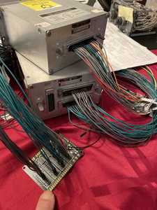
Dear Jay,
dear followers!
I want to follow Bill´s suggestion to start a new thread, instead of keeping it in the "Introduce Yourself" section, as it will be easier to reference it later. A great place to put this is the "Show & Tell" section in the "Project Corner".
I created the topic "BOEING 727-200 HOMECOCKPIT with original aircraft parts and instruments".
Therefore I want to discontinue the discussion in the "Introduce Yourself" section and continue in the "Show & Tell" section in the "Project Corner".
PLEASE USE THIS THREAD TO CONTINUE DISCUSSING THIS ISSUE.
At this point, I want to remenber, that I have two other threads on the ARDUINO Forum: SYNCHROS "SELSYNS" as Output Devices and SYNCHROS ”SELSYNS” as Input Devices.
Many thanks for your attention.
Peter
Hello Jay,
I was reflecting about your comments of AC / DC current (your post from Dec, 03).
„One thing that I’ve learned: The instruments/gauges’ lighting work best via AC voltage. I learned that DC voltage amps are very different than AC voltage amps in that AC amperage is much lower than DC.“
To reduce energy consumption and heat emission, I have substituted the bulbs by LEDs (where ever possible), as I mentioned earlier. Of course, for the instrument and panel ilumination, it was not possible.
As you see on the original OH-Panel, there are dimmers for MAP (2x), LEFT FWD & SIDE PANEL, CENTER FWD PANEL, FWD PANEL BACKGROUND, OVERHEAD PANEL and RIGHT FWD & SIDE PANEL. Originally there are installed Powerstat variable transformers (Pri. 28V, 380-420 cycl., Sec. 0-28V, 6 amps). Each of them is very heavy and I dond´t want to use them. I dond´t know, because they are 28 V, because the instrument lights and the background panel lights are running normally with 5V AC (or DC).
I was looking on the internet, how to dim AC bulbs. There are only dimmers for 220V or 110V AC available. Lower AC voltages, like 5V are not dimmable, because of TRIAC limitations, that cannot handle such low AC voltages.
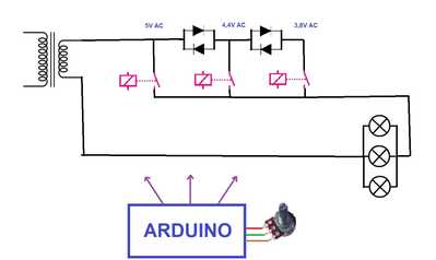
For this reason I will test the following circuit for, at least, stepwise dimming the 5V AC input voltage:
- Stepdown transformer 220V or 110V AC to 5V AC
- Antiparallel diodes in cascade (allowing the positve and negative sine curve to pass). Each diode pair should reduce aprox. 0.6 V.
- Relays
- Arduino should read the potentiometer position and activate one of the three relays.
At this moment, my PROPOSED CIRCUIT IS STILL NOT TESTED.
As soon, as I have some results, I will communicate.
Merry Christmas and stay safe,
Peter
Hey, buddy
I have tested my 28VDC to 115VAC/400Hz converter with a variable 5-30VAC transformer (the exact same one you have photographed here) all hooked-up to the dimmable lighting controls and can report that it works as advertised! Keep in mind, those overhead dimmer controls/rotary knobs are actually variable resistor controls and not rheostats/potentiometers as one might expect. In their current state, they will not properly work with DC voltage.
But…the entire scenario changes when LEDs are substituted for the ‘normal’ incandescent lights. I have heard that some home cockpit builders have swapped-out the installed variable resistor controls/rotary knobs in favor of rheostats with desirable results.
Personally, I’m at a loss to know which way I’ll proceed. I’m all for preserving power but I have to weigh the pros and cons of replacing incandescent lights with LEDs…it’s a lot of work and right now, am not entirely convinced this is the right path for me. I’ve converted maybe six (6) engine gauges and don’t really like the look of the new lighting. It’s okay—just not WOW, if that makes sense.
Let me know your thoughts—
All the best,
Jay
Hey Jay,
many thanks for your comments.
You have tested the original variable transformers with your 28VDC to 115VAC/400Hz converter. That´s great. I will not use the transformers, because I have only normal 60 Hz normal frequency. Aircraft and ships use 400 Hz, because it is possible to use smaller electrical components and wires. Therefore, I fear to fry the original transformer wirings. For me it´s OK to dim the bulbs in 2 or 3 steps. I have no need of dimming them continously.
Remarks: The only bulbs that I substituted with LED´s are the yellow, green, blue indicators on the panels, like for examle, on the PA subpanel.
I don´t recommend trying to do some work on the internal instrument ilumination, nor on the internal plate ilumination. It´s risky to damage something. These parts I will conect to 5V AC (60 Hz).
Greetings,
Peter
Peter,
That’s why I only did 6 engine instruments—I wasn’t entirely sure I wanted to do the remaining ones with LEDs. As I said earlier, I’m not really happy with the LEDs I’ve done and will be reconfiguring them back to their OEM condition. I did use 3 separate resistors per instrument using LED bezels which are glued to the metal light housing and the LEDs glued into the bezels. These can easily be removed…it’s just a very time-consuming process!!!
But, this is why we love this hobby…it is a lot of doing and undoing and re-doing!!
It’s great that you’ve got 5VAC/60Hz for the lighting. It sure beats having to do a lot of converting/transforming with extra components.
Jay
Jay,
fine that you could do the job on your instruments. I have some casings that I couldn´t open. That´s one reason, because I don´t want to force the instruments.
I only want to remember, that my PROPOSED CIRCUIT IS STILL NOT TESTED.
The diode arrangement must be checked.
5 VAC is perfect for normal light intensity and results in excelent low current flow, consequently low energy consumption and, as I hope, heat emission.
The study is going on.
Peter
Hello Jay,
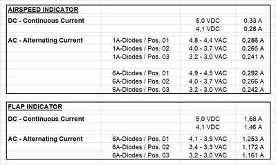
I did some tests with my 127 V/ 220V to 5 VAC transformer and had some interesting insights. I compared normal 5 VDC inputs with the 5 VAC at 60 Hz. I tested the bezel lighting of the AIRSPEED INDICATOR and the panel lighting of the FLAPS / SLATS INDICATOR. The dimming of the 5 VAC was realized with antiparallel diode pairs in cascade. The results of the voltage drop and current flows are listed in the table below. As expected, with each voltage drop, the intensity of brightness is reduced. The 1 A diodes warmed up a little bit (not much).
CONCLUSIONS:
- There is no specific reduction in current flow, comparing AC with DC.
- I would need big transformers to be used for all instruments in the aircraft panels which is not feasable for me.
- I will use 5V DC and PWM for dimming.
I will test MOSFET (IRF 520 module) or TIP 120 (or TIP 121) Darlington Transistors with the Arduino for dimming, as proposed by Bill on the DroneBot Workshop website:
https://dronebotworkshop.com/transistors-mosfets/
As soon, as I have more results, I will report.
Stay save.
Peter
Hi, Peter and Happy New Year!
Its incredible that you’ve done all this electronic testing for your AC/DC voltages and amps. The results you’ve posted are indeed interesting, to say the least. I am no where near ready to work on the internal lighting and lately, have been focusing my time and efforts in getting synchros to move. I have decided to just leave the OEM internal lighting in place and do not want to waste time retrofitting with LEDs.
I’m very happy to report that I was successful in getting the two (2) needles to move on an RMI instrument. I have three (3) units, one (1) for testing and the remaining two (2) for actual installation once the coding and testing on the first has been completed.
I’m using two (2) synchro transmitters hooked-up to the two (2) synchro receivers for the needles. Manually, I am moving the gear wheels on the transmitters which, in turn, are moving the needles. All are powered by my 115VAC/26VAC 400Hz inverter and I am VERY pleased with the results, thus far. I will be working on the compass card shortly and plan on using another synchro transmitter to accomplish this. Once the compass situation has been completed, I should be able to use the single synchro transmitter for ALL magnetic north reading instruments…each RMI, each HSI, each FD/ADI, etc. My thought here being…”Magnetic north is magnetic north in all compass-based instruments.”
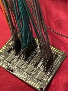
I will be driving all these synchro transmitters via gears, home position sensors and stepper motors. I have been communicating with a fellow simmer who pointed me in this direction of the steppers; his set-up and coding for these is nothing shy of miraculous! He has also helped me with the set-up and coding for the ATC Transponder, COM/NAV-1 and COM/NAV-2 radios. For these, I’ll be using Arduino, Teensy v4.1 and a Centipede Shield v2.0. The prospect is very exciting.
I do have a video of the RMI needles in operation, however, it is much too long to post here on the forum.
In the meantime, congratulations on your work to this point. I’m hoping that 2022 will be kind to us all with much success!
Jay
Hi, Jay and Happy New Year, too!
Glad to hear of your succes testing the RMI synchros. Your approch of using synchro transmitters and the 115VAC/26VAC 400Hz inverter is very close to the real conditions how these indicators work.
Success with your work!
Actually, I will continue working with the instrument ilumination on the Main Panel, maintaining the original 5VDC bulbs.
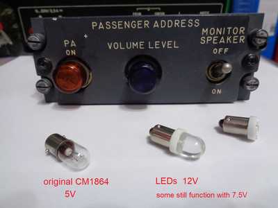
For the YELLOW, GREEN, BLUE and WHITE indicator lights, like on the PA-Passenger Adress module, or the AIRWAYS, MIDDLE MARKER and OUTER MARKER indicators, I will substitute the original 5V CM1864 bulbs with 12V LEDs, as shown on the following image. Some of these nominal 12V LEDs still work with 7.5V.
The better choice is the longer LED with the bulb, than the shorter, flat one. The flat one enters deep into the conector hole and is more dificult to fix correctly in the mounting.
Stay safe!
Peter
I remember my father (being an airline pilot) having to prep for his 6 month refreshers... I guess for emergency situations. He'd pulled out these life size paper-dolls color coded and sit down for extended periods practicing.
If I had the tools we have these days, I would have gladly made him 3D versions of his cockpit... maybe even program it to simulate emergencies.
GREAT PROJECT you have there!
3 lines of code = InqPortal = Complete IoT, App, Web Server w/ GUI Admin Client, WiFi Manager, Drag & Drop File Manager, OTA, Performance Metrics, Web Socket Comms, Easy App API, All running on ESP8266...
Even usable on ESP-01S - Quickest Start Guide
Hello Inq,
many thanks for your comment.
Stay safe,
Peter

