Test E
Ahhh! I wasn't totally wrong. Here, I turned on the lighting. I think it is a mix of fluorescent and sodium lighting. So, I now have a strange concoction of indeterminate make-up... but, I am seeing a 2m change in behavior between this and the Test D with just the ambient sunlight in the room. I'm seeing the delay again. It is similar to the 4 meter, but just not as pronounced.
After running the test as in the video, I switch off the square (sodium?) lights and the fluorescent lights are still on. The results are similar to Test D without any lighting.
3 lines of code = InqPortal = Complete IoT, App, Web Server w/ GUI Admin Client, WiFi Manager, Drag & Drop File Manager, OTA, Performance Metrics, Web Socket Comms, Easy App API, All running on ESP8266...
Even usable on ESP-01S - Quickest Start Guide
Hi @inq,
I like your experiments.. and I have a hypothesis.
.........
And Inq, I am sure you already know this, but in case anyone reading this is not familiar with the idea of a hypothesis, I hope you won't mind if I point out that in research it is common to get to a position where you are investigating something which you don't quite understand, but the limited evidence is suggesting an explanation, so you put forward the explanation, and then look for more evidence to support the explanation or to disprove it. It's a bit like a 'suspect' in a whodunnit story, but the evidence is not yet strong enough to prove they did it.
....
The sensor works by flashing the light source and waiting for a photon to return. (I use the word 'photon', because I have a suspicion it is looking for a singe photon per pixel, but it might be a certain number of photons ... the story is basically the same.)
To simplify the explanation, I am describing & considering just one (of the 64) pixels .. the other 63 will be playing the same game in their own field of view! Also I am using slightly approximated numbers.
It has a range of about 4 metres.. and we have seen distances up to just over 4 metres .. which is 8 metres there and back ... so let's assume that the sensor only accepts a photon which arrives after the flash, and has travelled not more than 9 metres.
Speed of light = 0.3 m /nanosecond (in air/vacuum)
Time to travel 9 m = 9 / 0.3 = 30 nanoseconds
Hence each pixel will have a time window of just under 30 nano seconds to 'spot' a photon, starting a short while after the flash, and finishing 30 nanoseconds after the flash.
From the video, I think there are 15 flashes per second.
So in 1 second, there are 15 opportunities for the pixel to 'spot' a photon in the time window and convert it into a time with respect to the flash.
What happens if the pixel doesn't see a photon in the 30 ns window?
My guess is that it repeats the result from the last window in which it actually spotted a photon.
This is a crucial guess if it is correct.
Imagine you have a movable 'wall-like' target which is large enough to fill the Field of View of the pixel for any distance up to (at least) 4 metres.
When the target is close to the sensor, say 300mm away, then a large proportion of the photons from the flash will be reflected back towards the pixel. The probability of a photon being 'spotted' by the pixel wil be very high, maybe 100%, so every flash will produce a new result..... the sensor display will be 'highly active' with data updates, and hopefully most will be 'close' to the 300 mm value.
(A few results may be less than 300mm, especially in the presence of ambient light in the right spectral region, but very few should be significantly greater than 300 mm, as the pixel wil always have spotted a reflected photon. Of course, there are other errors, so the actual cutoff distance could probably be a few percent either side of 300 mm.)
Now move the target to 4m from the sensor. The number of reflected photons entering the pixel sensor wil be very much lower, so that the chance of a photon being 'spotted' in a given 30 ns time window is now very low. If the pixel doesn't spot a photon, unfortunately it doesn't report 'No show' but instead reports the last value it was able to measure.
And by the look of your video, I would guess some pixels in the 4m test were only spotting about one photon every 5 seconds ... some even less.
Hence the display looked 'drowsy' and reluctant to update.
.............
How do you like the hypothesis? Do we have enough evidence to charge the accused?
Best wishes, Dave
Are there any relatively inexpensive single laser pointer type sensors available (say < $100 US)?
Bill compares the laser with sonar distant sensors.
https://dronebotworkshop.com/laser-vs-ultrasonic-distance-sensor-tests/
Again, this 8x8 sensor sounds like it would be ideal for obstacle avoidance compare to the ultrasonic.
Probably. I don't see ultrasonic being used in robot vacuums. IR and a simple bumper does the trick combined with a LIDAR system.
I'm afraid I am not sold on using this sensor for anything but close stuff and obstacle avoidance and I don't have your optimism of adapting a LISAR SLAM algorithm to use it to map a room.
The robot vacuum manufacturers have to build reliable and cheap solutions and they seem to favour the LIDAR system and the less reliable video camera, usually pointing up to the ceiling, to find reference points.
My interest has always been vision. My system if I get a video proof of concept working will not use maps to navigate a house.
I like the @daveE hypothesis on the slow response 🙂
@davee - I read it once, but the brain is mush from the those tests and the ones I haven't published yet concerning pixel FoV angles. I only do any useful analytical thinking in the morning. I'll need to study it.
3 lines of code = InqPortal = Complete IoT, App, Web Server w/ GUI Admin Client, WiFi Manager, Drag & Drop File Manager, OTA, Performance Metrics, Web Socket Comms, Easy App API, All running on ESP8266...
Even usable on ESP-01S - Quickest Start Guide
Are there any relatively inexpensive single laser pointer type sensors available (say < $100 US)?
Bill compares the laser with sonar distant sensors.
https://dronebotworkshop.com/laser-vs-ultrasonic-distance-sensor-tests/Again, this 8x8 sensor sounds like it would be ideal for obstacle avoidance compare to the ultrasonic.
Probably. I don't see ultrasonic being used in robot vacuums. IR and a simple bumper does the trick combined with a LIDAR system.
I'm afraid I am not sold on using this sensor for anything but close stuff and obstacle avoidance and I don't have your optimism of adapting a LISAR SLAM algorithm to use it to map a room.
The robot vacuum manufacturers have to build reliable and cheap solutions and they seem to favour the LIDAR system and the less reliable video camera, usually pointing up to the ceiling, to find reference points.
My interest has always been vision. My system if I get a video proof of concept working will not use maps to navigate a house.
I like the @daveE hypothesis on the slow response 🙂
I'll have to go through Bill's video at the library tomorrow, but I think the ToF sensor he used is similar in concept to this ST one. It has even a more limited range. I'll need to see if I can find a Lidar type one like goes on the turning versions. Maybe as they're used more on the vacuum cleaners, the price will come down. Did you see where iRobot was bought out by Amazon?
I think I see the mapping a little different in usefulness. I'll use the sensors to do the real-time local navigation. I see the mapping being like human memory. A person walks through the house and thinks where is the kitchen, bedroom, bathes... etc and get a lay of the land. I want the robot to figure out that lay of the land. And then when asked, go to the bathroom, it'll take a squat in the correct room. I also want it to be turned on and figure out what room its in so it knows where to start in its memory map and how to get to where it needs to go. I guess, I'm being optimistic that this sensor can do both... Micro and Macro navigation.
VBR,
Inq
3 lines of code = InqPortal = Complete IoT, App, Web Server w/ GUI Admin Client, WiFi Manager, Drag & Drop File Manager, OTA, Performance Metrics, Web Socket Comms, Easy App API, All running on ESP8266...
Even usable on ESP-01S - Quickest Start Guide
I read that "... the VL53L5CX can be programmed to automatically perform basic optical flow measurements by comparing sequential frames of data with an output of "motion intensity" per pixel. This is essentially a relative velocity field."
https://www.tindie.com/products/onehorse/vl53l5cx-ranging-camera/
This is something insects use and something I played with years ago. Of course I used a change in light intensity rather than a change in distance. I used 8 neighbouring pixel values to determine 8 different directions (of a moving edge).
Also on the same website,
"Furthermore, the wide 61° field of view means a full 360 degrees can be covered with just 6 sensors making collision avoidance for rolling or flying robots much cheaper and easier."
Another website with TOF projects and video that might interest you if you haven't already found it,
https://hackaday.io/project/180123-gesturepattern-recognition-without-camera-tof
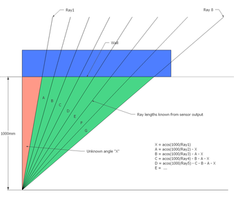
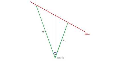
Here's the procedure I came up with to measure the angle between "pixels". As I was dinking around with the distance and lighting conditions having an affect on results, I realized I don't need to move blinders (tables on edge) in to see where the pixel's FoV were. I could simply use Trigonometry. Here's the graphic showing the geometry and resulting equations. You might note that the only critical setting is the distance from the wall. The angle relative to the wall can really be any angle. I rationalized trying to use a protractor or even trying to aim for a specific point on the wall would be like shooting in the dark. I feel I can easily get the wall distance within 1mm thus introducing less than 0.1% error.
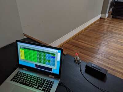
Here is an image of the rig setup relative to the wall.
In the results below, you'll see I ran six different tests. I angled it to three different angles so I could see if there were any bad behaviors at real oblique angles. @will - The results answers your earlier question, about reflecting away versus back to the sensor. I never saw any indication that a signal wasn't being received.
For each test, I created a client page that simply averaged up distances until they didn't change any longer. This often took minutes before every cell finally got an average that didn't change.
I noted after the first three tests that the "A" angle was way larger than the others. This was the one closest to the sensor and I wanted to see if it was a geometry problem with the setup or something physically wrong with the sensor. To test this theory, I simply flipped the sensor upside down. Thus the "A" column pixels were now furthest down the wall. As you see in the second set of results, I believe the answer is that there is a flaw in my sensor, not the test configuration.
Here's the actual spreadsheet for those so inclined see the equations.
Note, all the bright colored cells are for the same angle. Also note how column "A" (RED) is twice the size of the other angles. The sum of the pixel FoV is shown in the Excel column "J" and shows a pretty good correlation to the datasheet's speck of 45 degree sensor FoV.
I probably should now try it for the vertical, by placing the sensor on its side. With these numbers I'll now be able to use the ray angles to translate the sensor spherical coordinate system to a 3D global cartesian coordinate system for the mapped space.
VBR,
Inq
3 lines of code = InqPortal = Complete IoT, App, Web Server w/ GUI Admin Client, WiFi Manager, Drag & Drop File Manager, OTA, Performance Metrics, Web Socket Comms, Easy App API, All running on ESP8266...
Even usable on ESP-01S - Quickest Start Guide
Maybe as they're used more on the vacuum cleaners, the price will come down.
A video camera doesn't cost much and provides plenty of data. Software may cost to develop but after that it is a simple copy process so again cheap to process all that video data. Some robot vacuum cleaners like iRobot have used a camera to find features to map and navigate using a process called visual SLAM.
TOF might well be a useful adjunct to vision.
To experiment with visual SLAM you can structure the environment with easy to distinguish features. These can be shapes, color, light points (leds of different colors), bar codes and so on. The example I gave in another thread was a simple "target" that can be tracked in real time. Sorry no video I would have to sign up to utube to provide that. The still images shows how the software can put a rectangle around the target (or many targets within the image) and return its position in the image. The size of the rectangle gives a distance measure which becomes more accurate the closer the camera is to the target. A distortion of the rectangle can provide an angle measure to the target (see last image). Ideally you would use "features" like perhaps the door knob or the vertical lines and corners.
To enlarge an image, right click image and choose Open link in new window.
However all that is for another thread. Not much interest using vision in their robots was shown so I didn't post anything more about it.
With these numbers I'll now be able to use the ray angles to translate the sensor spherical coordinate system to a 3D global cartesian coordinate system for the mapped space.
Congratulations on your persistence using this sensor and the experimental work you are doing. I will be interested to see if you can map a building using the sensor alone.
Bill compares the laser with sonar distant sensors.
https://dronebotworkshop.com/laser-vs-ultrasonic-distance-sensor-tests/
I've now checked Bill's topic out. The ToF sensor is basically an earlier one of the same style as the single pixel VL53L0X... predecessor to this 8x8 version. So they still have the same constraints.
I just got on Amazon and searched for Lidar. The spinning ones are also not using laser pointers... their beams FoV are 2 degrees. Thus at the given max range of 12 meters, the single beam is looking at a 400 mm diameter area. One manufacturer even admitted that the if something close was in part of that area and another thing further behind, the value would be indeterminate. They didn't claim an average... just indeterminate. Although clever and perfect for a robovac, I think I'd prefer the single beam ones with the rotation mechanism and totally control where it is pointed by mechanisms. I need to point it up to get the walls above the spinning disk. Tilting the disk, just makes it all that much harder to throw away the angle going into the floor. Something like:
"https://www.amazon.com/SmartLam-TP-Solar-Proximity-Distance-Raspberry/dp/B09B6Y2GBJ/"
https://www.amazon.com/SmartLam-TP-Solar-Proximity-Distance-Raspberry/dp/B09B6Y2GBJ/
These also only use lens to focus the beams, and doesn't use a laser pointer beam. They also state a 2 degree FoV.
3 lines of code = InqPortal = Complete IoT, App, Web Server w/ GUI Admin Client, WiFi Manager, Drag & Drop File Manager, OTA, Performance Metrics, Web Socket Comms, Easy App API, All running on ESP8266...
Even usable on ESP-01S - Quickest Start Guide
The still images shows how the software can put a rectangle around the target (or many targets within the image) and return its position in the image. The size of the rectangle gives a distance measure which becomes more accurate the closer the camera is to the target.
OK... I get it now. You're using a known sized object to then calculate its distance based on based on the video image FoV and a scaling factor.
3 lines of code = InqPortal = Complete IoT, App, Web Server w/ GUI Admin Client, WiFi Manager, Drag & Drop File Manager, OTA, Performance Metrics, Web Socket Comms, Easy App API, All running on ESP8266...
Even usable on ESP-01S - Quickest Start Guide
Congratulations on your persistence
You beat your head against a wall long enough, the wall's got'a give!??
🤣
3 lines of code = InqPortal = Complete IoT, App, Web Server w/ GUI Admin Client, WiFi Manager, Drag & Drop File Manager, OTA, Performance Metrics, Web Socket Comms, Easy App API, All running on ESP8266...
Even usable on ESP-01S - Quickest Start Guide
If distances D1 and D2 and angle A are known can't you calculate the 1000mm distance of the sensor from the wall?
To enlarge image, right click image and choose Open link in new window.
I was about to do a gut belch that it's the average, but that's not right. I'll have to sit down and work it out, but yes, it is determinate. I'm about to start a tutoring session with a student and then later I have our local user's group. We might start the Animatronics project tonight. It might be another insomniac session. 😎 😉
One thing to note about the test and geometry above... it ONLY tells us the FoV angle of each pixel. It doesn't tell us if its measuring the wall a the middle of the pixel (average) or closest. However... as I right this and your geometry question... something's itching the back of my neck that I can deduce whether its at the center or nearest. But then... maybe you are that far ahead of me and are posing that question to start us down that rabbit hole.
Noting the percent error in that spreadsheet, I wonder how noisy that point cloud is going to be... making it that much harder to statistics to ferret a wall out of the scatter.
VBR,
Inq
3 lines of code = InqPortal = Complete IoT, App, Web Server w/ GUI Admin Client, WiFi Manager, Drag & Drop File Manager, OTA, Performance Metrics, Web Socket Comms, Easy App API, All running on ESP8266...
Even usable on ESP-01S - Quickest Start Guide
Looking at the curvature in the data maybe the sensor is pointing down a bit?
The sensor appears to be looking at the wall at an angle of about 15 degrees?
The further the distance the more erratic the data.
To enlarge an image, right click image and choose Open link in new window.
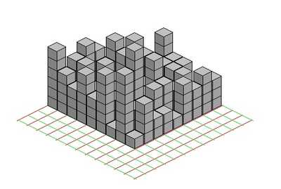
You might try using a block display which Excel should be able to do rather than color codes?
This is just a isometric random data example of what I mean.


