" ... taking the 8x8 distances from the ToF, an X,Y,Z of the bot in some global coordinate system and an azimuth of the bot and a further angle of the head should be a one-liner to start spraying the point cloud."
It will be interesting to see if it is really that easy 🙂
Converting relative coordinates to an absolute coordinate system requires you know the pose (location and rotation of the robot) in that absolute coordinate system. How do you decide if whatever your gyro mag or encoder has a correct pose to start with to spray into the global point cloud space? In the algorithms I have seen when the robot comes back to where it was once before it uses any mismatch to move the global pixels so they link properly.
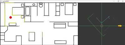
In the 2d example below there are are up to 360 distance values. The image at the right is what the robot would "see". It has to match what is sees to the global pixels on the left. But first has to build up the image on the left to create a map to use in the first place.
In the example below I have run through the 360 distance data points to connect close pixels on the assumption they belong together (as shown by the color). The next step is to break the list of connected (by distance) points into things like corners which can be tracked by matching the coordinates of a corner in a point list to the nearest coordinates of a corner in the next set of point lists. The lines also have a direction which can be used to track rotation of the robot.
I am dealing with lists of points not with the image itself which is there for the human visual system only.
To enlarge an image, right click image and choose Open link in new window.
It will be interesting to see if it is really that easy
Converting relative coordinates to an absolute coordinate system requires you know the pose (location and rotation of the robot) in that absolute coordinate system. How do you decide if whatever your gyro mag or encoder has a correct pose to start with to spray into the global point cloud space? In the algorithms I have seen when the robot comes back to where it was once before it uses any mismatch to move the global pixels so they link properly.
I did say in that paragraph that the position and angles in that global coordinate system (the pose) were givens, then it becomes a matter of doing a one-liner of matrix multiplication. A transform matrix would be created that has all the translation and rotation inputs. The 8x8 would be a matrix of 64x3. The one liner is multiplying the two matrices.
Results = Transform * ToF;
However, one thing came up after writing that. I did that post for 1m data in the ToF thread. I started doing the 2m data and many of the cells are invalid. So, you're correct... the one-liner will have to be increased to populating that ToF matrix based on ONLY valid entries... thus a loop and an if statement will be required. It's grown by 300% to (I'm thinking now) 3 lines. 😉
Now the part about deciding what to trust the most ToF data, gyro, mag, or stepper dead-reckoning or some composite... that is a big can of worms that I don't have a plan through yet.
I was studying some YouTube's the other day. I don't know if this is a link I got from you or even on this forum, but I found in intriguing for several points...
- It talks about that completing the "loop" and having to bend the entire path around to resolve that the end point and start point (being the same) did not match up.
- He used a far more sophisticated piece of hardware with a true spinning gyro, spinning Lidar AND Vision and it still was off a great deal. I'm wondering just how far I'm going to get with equipment that is 1/100th and maybe 1/1000th the price.
- He did not talk about what they did with the point cloud. So far, all I've seen is that the point cloud is the end-product and isn't really utilized downstream for any AI type reasoning. I expect that it has to be condensed down to form boundaries and points of interest like you're talking about here.
In the example below I have run through the 360 distance data points to connect close pixels on the assumption they belong together (as shown by the color). The next step is to break the list of connected (by distance) points into things like corners which can be tracked by matching the coordinates of a corner in a point list to the nearest coordinates of a corner in the next set of point lists. The lines also have a direction which can be used to track rotation of the robot.
VBR,
Inq
3 lines of code = InqPortal = Complete IoT, App, Web Server w/ GUI Admin Client, WiFi Manager, Drag & Drop File Manager, OTA, Performance Metrics, Web Socket Comms, Easy App API, All running on ESP8266...
Even usable on ESP-01S - Quickest Start Guide


