Small Pico Based Robot
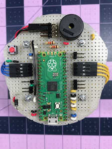
I’ve been working on a super small (for me) robot using the Pico. Here’s a pix of the main board.
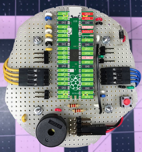
At the top of the picture is a row of double right angle headers. These are connected to the 3.3V pin on the Pico and provide power to the motor driver logic board and the IR sensors. Below that is the voltage sensor which is implemented as a voltage divider connected to the ADC2 pin. The red button is a momentary switch connected to the RUN and GND pins. A Schottky diode sits between the battery and the VSYS pin. And finally an oversized piezo buzzer. The buzzer gets its PWM signal from GPIO 6.
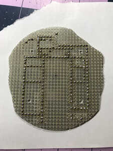
I used 28 AWG bus wire on the bottom side to tie most of the common ground pins together. The 3.3V bus and voltage divider also have some traces tying things together. Here is a pix of the initial work.
The ADC GND is connected to the voltage divider circuit and the bottom two GND pins on the 3.3V bus. According to the documentation there is circuitry in the ADC GND to calm the beast a bit.
When I started programming the board I immediately noticed that I had forgotten to add a momentary switch that grounds the RUN pin. So I retro fit one last weekend.
The only bummer with this layout is that I’ve blocked access to the ADC VREF pin :/
Tom
To err is human.
To really foul up, use a computer.
Are you programming it in microPython or C++?
A picture (a circuit diagram) is worth a thousand words.
I think in images as I get lost with a verbal description.
To enlarge an image, right click image and choose Open link in new window.
I like that overlay! I’m forever reaching for the Pico pinout chart.
I have a surprising amount of Arduino code that I’ve written and tested over the years so using C on the Pico was a no-brainer for me. Although, I have to admit that just this morning I found a bug in a rotation calculation. LOL
Tom
To err is human.
To really foul up, use a computer.
Post Script
If and when I do this over again I would add a bare wire loop that is big enough for an alligator clip and connect it to the battery ground. With something like that in place it would be a whole lot easier to check the state of the battery during testing and development.
Tom
To err is human.
To really foul up, use a computer.
I finally finished unit testing a new PCB that will replace the protoboards that I’ve been using to built my small robots. I used KiCad to design and OSHPark to fabricate the PCB. I had to upgrade my soldering kit as well in order to solder a TSSOP-16 package. I bought a Weller made in Mexico and it’s been great!
Here’s a clockwise run down of what’s on the board:
12:00 - is a USB connector for powering the battery charger. U2 is the MCP73831/2 charge management controller.
01:00 - is a piezo buzzer for making annoying sounds.
02:00 - is a momentary switch that grounds GPIO15. When this pin is pulled low at boot time it places picowota in bootloader mode, where it waits to receive new application code.
03:00 - the battery power switch, D2 is a Schottky diode.
04:00 - J3 is a JST-PH connector that supports a I2C connection and power/ground from the battery. Used for connecting a Pico-W based sensor board.
05:00 - three colored LEDs. Red, Blue, and Green.
06:00 - the star of the show, a RPi Pico-W.
07:00 - R3 and R4 used as a voltage divider to give a rough battery voltage reading.
08:00 - J5 is a connector to the right wheel, used for power and to read the wheel encoder
09:00 - U3 is the DRV8833 DC motor driver. I’ve been using the DRV8835 for years but the package is tiny, so I opted for this TSSOP-16 package. It is the hardest component to solder to the board, Sadly, I’ve burned a few along the way :/
10:00 - J4 is a connector to the left wheel.
11:00 - J2 is the JSH-PH connector for the Li-Ion battery.
Not a lot different from what I’ve been doing, just a much smaller footprint and a lot easier to assembly. If anyone is interested I can post the KiCad schematic document.
Tom
To err is human.
To really foul up, use a computer.
I source my wheels, motors and encoders from Pololu Robotics & Electronics. Which in turn gets them from China. I noticed that the Arduino Alvik Robot that our host created a video about uses the same wheels, motors, and encoders.
Tom
To err is human.
To really foul up, use a computer.
I finally finished unit testing a new PCB that will replace the protoboards that I’ve been using to built my small robots. I used KiCad to design and OSHPark to fabricate the PCB. I had to upgrade my soldering kit as well in order to solder a TSSOP-16 package. I bought a Weller made in Mexico and it’s been great!
Here’s a clockwise run down of what’s on the board:
12:00 - is a USB connector for powering the battery charger. U2 is the MCP73831/2 charge management controller.
01:00 - is a piezo buzzer for making annoying sounds.
02:00 - is a momentary switch that grounds GPIO15. When this pin is pulled low at boot time it places picowota in bootloader mode, where it waits to receive new application code.
03:00 - the battery power switch, D2 is a Schottky diode.
04:00 - J3 is a JST-PH connector that supports a I2C connection and power/ground from the battery. Used for connecting a Pico-W based sensor board.
05:00 - three colored LEDs. Red, Blue, and Green.
06:00 - the star of the show, a RPi Pico-W.
07:00 - R3 and R4 used as a voltage divider to give a rough battery voltage reading.
08:00 - J5 is a connector to the right wheel, used for power and to read the wheel encoder
09:00 - U3 is the DRV8833 DC motor driver. I’ve been using the DRV8835 for years but the package is tiny, so I opted for this TSSOP-16 package. It is the hardest component to solder to the board, Sadly, I’ve burned a few along the way :/
10:00 - J4 is a connector to the left wheel.
11:00 - J2 is the JSH-PH connector for the Li-Ion battery.
Not a lot different from what I’ve been doing, just a much smaller footprint and a lot easier to assembly. If anyone is interested I can post the KiCad schematic document.
Tom
Nice. Where did you print this PCB from?
What do you mean by "print" ?
He says "I used KiCad to design" which specified what he used to lay out the circuit and its parts.
He says "and OSHPark to fabricate the PCB" which probably means that's where he sent the information where the Gerber files were used to create the PCB.
So it's not clear to me what you meant by "print the PCB" ?
Anything seems possible when you don't know what you're talking about.
Hi @aliarifat
This is a link to the OSH Park web site. https://oshpark.com I used their ‘Prototype’ service. I started with a couple of small boards: 1) an IR proximity sensor and 2) a breakout board for the DRV8833 motor driver before I went with the 86mm diameter board. They won my business when they let me re-submit a design where I hadn’t understood the fine points of the minimum slot size supported. I’m a customer for life!
Tom
To err is human.
To really foul up, use a computer.
As you need many bots to demo swarm behavior the cost per robot would be a factor at the hobby level so how much would it cost for your design?
I would think being able to download experimental programs from you pc to the bots would be something worth implementing?