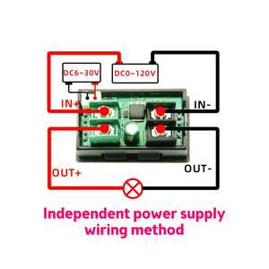
Those V/A displays have been around for while it seems although I only found out about them two years ago, I have two, temporarily used one for another power supply project (before I removed it), was wired with with its own dedicated power source.
I recently found a newer display that seem to be more user friendly, easier to follow wiring diagram, ordered one to see if it is indeed different from the cheaper/ ubiquitous one:
Edited to add the following comment:
I meant I hope I could use this newer "tester" as a display but I'll find out soon.
Ken from Peterborough
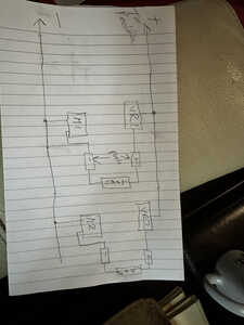
@davee Same meters as Bill, I see no issues. If I ever find a drawing program I can use, I will post a circuit, but it's fairly obvious. From the rectifier, run a positive and negative bus. between the bus's install the LDO VR circuit and the meter. Rinse wash repeat for 3 more voltages. each meter has a separate path as does the VR. I will also install a meter for the entire current measuring the rectifier output.
First computer 1959. Retired from my own computer company 2004.
Hardware - Expert in 1401, and 360, fairly knowledge in PC plus numerous MPU's and MCU's
Major Languages - Machine language, 360 Macro Assembler, Intel Assembler, PL/I and PL1, Pascal, Basic, C plus numerous job control and scripting languages.
Sure you can learn to be a programmer, it will take the same amount of time for me to learn to be a Doctor.
@davee I thought I already posted to this, but my internet will be repaired in a couple of days. I am using the same meter. Each meter has a separate path to the rectifier negative.
First computer 1959. Retired from my own computer company 2004.
Hardware - Expert in 1401, and 360, fairly knowledge in PC plus numerous MPU's and MCU's
Major Languages - Machine language, 360 Macro Assembler, Intel Assembler, PL/I and PL1, Pascal, Basic, C plus numerous job control and scripting languages.
Sure you can learn to be a programmer, it will take the same amount of time for me to learn to be a Doctor.
@ddistrbd1 That is a different meter.
First computer 1959. Retired from my own computer company 2004.
Hardware - Expert in 1401, and 360, fairly knowledge in PC plus numerous MPU's and MCU's
Major Languages - Machine language, 360 Macro Assembler, Intel Assembler, PL/I and PL1, Pascal, Basic, C plus numerous job control and scripting languages.
Sure you can learn to be a programmer, it will take the same amount of time for me to learn to be a Doctor.
Hi Ron @zander,
Each meter has a separate path to the rectifier negative.
That is true ... it is the consequence that is important ... for the meters of the type specified by Bill, there is a resistor between the thick Red and Black wires of the meter, not just a piece of wire. With only one output and meter, as in Bill's design, it is of no consequence. But when you try to have multiple meters for multiple outputs, it can easily get in a mess.
As you haven't published a drawing your full specific intended implementation, I can't be sure whether or not my concerns will affect you. I wish you well with your project ... I was only trying to warn that you need to take care with your design, and understand the limitations of the situation, as it would be easy to build a circuit which 'nearly works' but has strange behaviours.
Best wishes, Dave
PS I have noted the different meter that @ddistrbd1 found ... unfortunately I haven't been able to find any information about its internals, so it may or may not have the same limitations.
@davee I appreciate your concern. When I build it I will test it. I might remember to post a followup but don't count on it.
First computer 1959. Retired from my own computer company 2004.
Hardware - Expert in 1401, and 360, fairly knowledge in PC plus numerous MPU's and MCU's
Major Languages - Machine language, 360 Macro Assembler, Intel Assembler, PL/I and PL1, Pascal, Basic, C plus numerous job control and scripting languages.
Sure you can learn to be a programmer, it will take the same amount of time for me to learn to be a Doctor.
@davee I think you must be thinking of some other wiring arrangement, The meter resistance is added to the load if connected for one specific voltage. Other than dropping a part of the power supply voltage across the meter resistor I see no effect on any other VR/Meter combination.
First computer 1959. Retired from my own computer company 2004.
Hardware - Expert in 1401, and 360, fairly knowledge in PC plus numerous MPU's and MCU's
Major Languages - Machine language, 360 Macro Assembler, Intel Assembler, PL/I and PL1, Pascal, Basic, C plus numerous job control and scripting languages.
Sure you can learn to be a programmer, it will take the same amount of time for me to learn to be a Doctor.
Ken from Peterborough
Hi Ron @zander,
You are right, in the arrangement you show, there isn't a problem ... as I said previously ..
If the two loads are electrically isolated from each other, this is still fine, but if they were connected in some way, their private "0V" lines would be at different potentials ... not a good situation in general, that is likely to lead to all sorts of issues!
The rabbit holes are in the 'but' ...
A typical problem that could arise is that you may wish the two loads to be interconnected by a data bus, such as I2C. How do they make a ground wire connection that doesn't connect the two negative lines together?
---------------
Another version of same basic concern ... Bill's original power supply box sensibly connected the 'Earth' wire to the output negative terminal, so that it would be the same 'Earth' potential as all of the other 'Earthed' appliances. Until you drew a diagram, I could only assume that you would follow Bill's lead.
Where would you connect your incoming mains 'Earth' wire connection to?
If it is not 'mains Earth', then you need to make sure that a unit powered by your supply never makes a connection to something like a (mains powered) PC with a USB cable, as that is likely to be referenced to mains Earth.
The list of possible rabbit holes is almost endless.
-----
Of course, both of my points are not the only possible wiring arrangements one could propose ... your sketch is an alternate, as I discussed previously, but for a general purpose power supply in particular (which is what I presumed Bill intended) that is likely to be used in different scenariois, I think my concerns could be troublesome.
But perhaps you have a specific 'hard wired, never changed set of loads' application in mind, that fits your sketch, in which case all should be fine.
Best wishes, my friend .. take care of yourself ... I am not trying to score points ... just trying to save you from some possible problems in the future,
Dave
@davee Ok, I think we call it a ground loop as we say ground where you say earth. Yes, I left out the mains earth goes to the case, which is part of that excellent power/fuse switch Bill specified and of course, the NEG posts are grounded like Bills. Let me know if you see a problem.
I have been trying to locate a circuit drawing program that doesn't try to also do a bunch of extra stuff but so far, no luck. Fritzing comes close, but I can't figure out how to find the pieces I need. My needs are small, a resizable box works for me for most components. Resistors and capacitors are nice to have but I can live with skinny boxes and if circles are available that will do for caps, otherwise square caps. I don't want to spend more time drawing the circuit than building it, just not important to me, BUT I do understand it is needed for effective communication, and that is why I continue to search. Thank you for your patience.
First computer 1959. Retired from my own computer company 2004.
Hardware - Expert in 1401, and 360, fairly knowledge in PC plus numerous MPU's and MCU's
Major Languages - Machine language, 360 Macro Assembler, Intel Assembler, PL/I and PL1, Pascal, Basic, C plus numerous job control and scripting languages.
Sure you can learn to be a programmer, it will take the same amount of time for me to learn to be a Doctor.
Hi Ron @zander,
I hope you agree that connecting the NEG pin to ground (mains Earth) is a good idea and you intended to do it on your actual unit. The problem is you can only connect to one NEG output, without hitting a rabbit hole.
If the thick red and black wires were directly connected together inside the meter, then you would be creating a classic ground loop ... not good, but often ok, and you probably have only had a problem if you used it with something like an audio amplifier which is likely to have 'hummed'.
But the wires are actually connected via low value resistor, which is the ammeter's shunt. So if you connect two NEG outputs together, either inside your power supply box or outside via the wiring, you are effectively putting these shunts in parallel, so they will be unable to correctly report the current of their own supply voltage. If you had wired (say) five of these meters like this, then they would all have reported the same current ... one-fifth of the total actual current.
In addition, if one circuit was powering a high current load, and another a sensitive low current load, perhaps for measuring something, it is quite likely the measurements would be corrupted by the high current load surges, and in some cases may have even caused the whole thing to oscillate.
There are many variations of how you might connect these current meters, and hence different consequences, but fundamentally they only work when each output has its own isolated load ... Ok for something like a lightbulb as each load, but when dealing computer controlled things and also with audio stuff, connecting units together, and/or connecting the metalwork to earth for safety and screening reasons is very common.
Best wishes, Dave
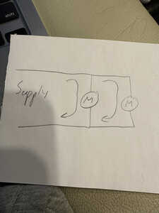
@davee Thank you for your concern, but I don't see it. As far as I can see, I have totally separate independent paths, BUT I will test by using a clamp on meter to verify each meter reading. I think my poor diagramming technique is causing you to misunderstand, that is my issue, and I am working on it. One last try with a very simple, super high-level diagram. Just treat the entire VR circuitry, meter as a single black box. 2 in parallel are isolated and if you cause me the slightest doubt, I have a good supply of diodes to insert in the appropriate legs.
First computer 1959. Retired from my own computer company 2004.
Hardware - Expert in 1401, and 360, fairly knowledge in PC plus numerous MPU's and MCU's
Major Languages - Machine language, 360 Macro Assembler, Intel Assembler, PL/I and PL1, Pascal, Basic, C plus numerous job control and scripting languages.
Sure you can learn to be a programmer, it will take the same amount of time for me to learn to be a Doctor.
Hi Ron @zander,
I think you need to remember how an ammeter works (the 'traditional' type, excluding those like your clamp meter that use Hall effect, and also excluding current transformers that only work with AC). You put a low value 'shunt' resistor in series with the circuit and measure the voltage drop across the resistor. This is how the ammeter in Bill's PSU works.
This means, if you have (say) 5 ammeters, each measuring different circuits, you have 5 differing voltage drops.
All 5 are commoned at the rectifier/smoothing capacitor negative pin.
If you also common them at the NEG outputs, then you have just paralled all 5 shunt resistors.
If you do not common them at the NEG outputs, how would you connect to Earth as per Bill's PSU?
Other configurations can also be suggested, but they all have problems, with the possible exception that each output has a single load which is always isolated from everything else.
Diodes or whatever cannot change the situation.
Sorry, but the best shunt based solution is to measure the 'high side' current, by putting the shunt in the positive output ... unfortunately that would require significantly changing the ammeter circuit, which would be far from easy in this case.
Best wishes, Dave
@davee Sorry Dave, I simply do not see it. When I build it I will test it
EDIT: Now I see where we differ, I am NOT 'commoning' the NEG outputs. The NEG output jack is attached to the meter red wire.
First computer 1959. Retired from my own computer company 2004.
Hardware - Expert in 1401, and 360, fairly knowledge in PC plus numerous MPU's and MCU's
Major Languages - Machine language, 360 Macro Assembler, Intel Assembler, PL/I and PL1, Pascal, Basic, C plus numerous job control and scripting languages.
Sure you can learn to be a programmer, it will take the same amount of time for me to learn to be a Doctor.
Hi Ron @zander ,
Re: I am NOT 'commoning' the NEG outputs. The NEG output jack is attached to the meter red wire.
Ok so if you have (say) 5 Ammeters, then you wil have 5 NEG terminals ... so far you are ok.... this is still in the 'isolated loads' case.
The concerns arise when you start to use the PSU, as it is likely two or more NEG terminals will get connected together in some way.
---------------
If any of the following EVER deserve a YES answer, you are heading towards a rabbit hole...
- Are your outputs referenced/connected to mains Earth? If so how are they connected to Earth?
- Will you ever use your PSU to power a unit that needs more than 1 voltage output from your PSU?
- Will you ever power two units from different outputs, that also have a connection between them .. e.g. I2C datalink?
- Will you ever connect a unit powered by your PSU to something else, that is mains powered, e.g. a via a USB cable?
---------
Best wishes,
Dave


