Hello Folks,
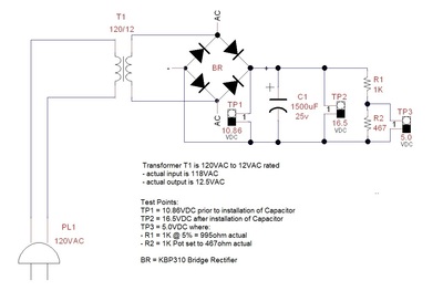
I'm trying to relearn electronics again and having some conceptual difficulties. I have attached a diagram of a power supply I have been working with. It's early in the development and will be attaching 3 power regulators to in the future but just playing with trying to understand "simple" concepts first.
I am confused over the readings I am getting for voltage at various points on the attached circuit. As you will see on the attachment, my meter reads a supply voltage of 118VAC at the wall outlet and the transformer with out load is reading 12.5VAC. I attach this to a bridge rectifier and check the unloaded voltage at the output pins and get 10.86VDC. When I connect any capacitor below the shown 1500uF Electrolytic capacitor, the capacitor will blow. I am using 25v rated caps and thought that would suffice since I thought the circuit would produce only 12VDC. With the 1500uF cap, I am getting 16.5VDC which is really confusing me. Can't find any explanation for this in Google searches or in my two electronics text books.
At the voltage divider, I want a 5.0VDC reading which will be used to power a small ADC circuit on the Atmega 328P chip. My calculations using an online Ohms law calculator show different values required for R2. Starting to wonder if there is something wrong with my volt/ohm meter.
Anyone have thoughts or an explanation for why this circuit is behaving this way? Any pointers will be greatly appreciated.
Thanks,
Brian
The bridge rectifier is causing a 2v or so drop from the internal diodes.
Usually, you would want to use a film capacitor rated @ 250VDC or so.
Thanks for the confirmation about the voltage drop on the bridge. I thought that may be the case but wasn't able to understand that from the datasheet. Lots to learn.
I'll check into the cap you mentioned. Why does the voltage increase after the electrolytic cap is installed?
Thanks for the input. Greatly appreciated.
Brian
It's been a long while since I looked at this 🙂 There is a ratio you used to calculate the AC into the rectifier and the DC out. 1.4 or 1.6 is ringing a bell, but don't quote me on that.
Now, electrolytic caps have a "floating" capacitance and that can shift during the life of a circuit being on, temp, and the age of the cap. It can be a big shift and is why tantalum is used (if you can in that place) or a larger cap. Now again, please don't quote me on this. Use it to google and find a better answer 🙂
If it were me, I would take the output of the rect/cap and feed it into a linear regulator close to the voltage needed. This is usually what you want to do going into digital circuits from mains.
Hope this helps.

