Hi all!
I am working on one of my projects and I want to be able to connect one or more battery packs to a few rails to use for several power users.
The goal is to be able to connect any and all packs to any and all rails, and the power user will be connected to the selected rail.
In essence it will be a matrix between the packs and the rails, and a (little) matrix between the rails and the users.
Now I will be switching the positive in all cases, ground will be common for all electronics on board.
Usually P-channel MOSFETs are used in such a case, but I would like to try to use N-channel, since I think I can work with the cons, and the pros are worth it.
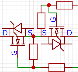
In the following drawing we have the MOSFETs in series:

On either side the drain will be connected to either a battery pack (the BMS actually) or a rail.
The resistors on the gates lead to a pair of optocouplers which in turn switch it to a higher voltage than on the source (I will come back to that in a bit).
When an optocoupler conducts, the corresponding gate will be high enough compared to the source that the MOSFET will switch on and conduct the power in a single direction, using the zener in the other MOSFET to bypass it.
The con is that this will probably mean a higher voltage drop, since the zener is not as good as a schottky you can use like in the next solution, the pro is you do not need that schottky (less components).
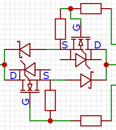
The next puts the MOSFETs in parallel:

The same applies as for the one in series, but the zeners in the opposing MOSFETs are replaced by schottky's of their own, making it possible to limit the voltage drop.
That is the pro, the con is more components, and since the MOSFETs I'm going to use are in the TO-220 package and the schottky's that are capable of handling these kinds of power are as well, that means a doubling of TO-220 packages.
Another pro is that this makes the two directions independent from each other, but I do not think that is something I will worry about, since I can easily move a pack to another swtich while I repear the broken one.
On to some of the numeric details.
The power users will be two PWM/buck/boost converters which will be supplying a controlled voltage to two brushed DC motors, each capable of drawing 10A at 24V.
The others will be possibly other packs, to balance voltages or a DC-AC inverter and the control system.
(There might be others, but that's for a later time, when this problem is solved.)
The battery packs will be 7S5P or 8S5P of 18650's, depending on how I am going to design the power users. I have a few 20A BMS's, but I need more and if the packs can handle it, I want to make that 40A or even 60A, depending on if the MOSFETs are affordable (compared to the ones I currently like for this, which can do 40A easily).
If it is necessary / cheaper / more to my liking I could build the BMS's myself, especially if I can integrate them with the next that makes these packs NexGen:
Each pack will have a control system, that will keep an eye on the voltages (full pack and individual parallel strings of 18650 cells), current it sources and drains, the temperature on multiple sides of the pack, gyroscope (detect falling and such) and possibly some other things, and sends it to the central control system, that keeps a log and can switch between packs to power the users.
There will be between 20 and 24 packs, and 4 rails to switch between, and each connection should be possible independently from the others.
I said I would come back to the higher voltage, which will be used to switch the gate to on, and this is my reasoning how I can establish this:
In most MOSFETs, and certainly the one I like, VGS(TH) is 4V (but something like 10V is better with a lower RDS(ON)) and VGS is 20V, so I just need to find a voltage that will will be high enough compared to the source.
Since the source will be the voltage drop over the schottky (assume 1V) lower than the pack's voltage, it will be between 21.4V and 28.4V, so a gate voltage between 38,4V and 41.4V would be good and within the limits.
I am going to generate this voltage (still relative to the ground) with some boost converter, it does not to supply any kind of serious power, since it will only be used to switch the MOSFETs on.
Whether the resistors between the gates and the switch voltage are necessary I do not know, but I have seen it being implemented to reduce the current that flows when the MOSFET is switching on. If they are necessary, the switch voltage will have to be higher to compensate the voltage divider consisting of the resistor between gate and source and the resister between gate and the switch voltage.
(The optocouplers also cause a voltage drop, but that is not relevant to the case, I just have to add this drop to the switch voltage.)
The MOSFET I like for this (because of low price, high current, high voltage and quite low RDS(ON)) is the STP75NF75 and the schottky diode (for the parallel version) is the MBR30100CT or MBR60100CT (the first if it is enough, if not the second).
Now my questions to you all are:
- Do these two circuits even work as I expect them to do?
- What values do I have to choose for the resistors (ballpark figure)?
- Should I go for the series or parallel option?
- Is it possible use a negative VGS that is VS lower than VS to switch the MOSFET off?
For question 3 I like to get facts and arguments, but the voltage drop and number of components are probably not decisive points for me.
Gabor
Maker Novice
Recently I have found that in cases that MOSFETs are put back-to-back as in the series option, it is usual to put schottky's in parallel with the MOSFETs, to limit the voltage drop.
Since that seems to be the case the difference is not the schottky's anymore, so I will drop the series option, since that is limiting somewhat.
By now I have moved the resistors between the gates and the switching voltage to the driving part (with the optocouplers), so it is possible to use resistor arrays with a common pin (which will go to the switching voltage).
I am still not completely sure if they are necessary, but it's easy enough to omit them at any stage of the development.
On the one hand I want the system to waste as little power as possible (through resistances/voltage drops/whatever), on the other hand I want it to be very flexible, so I will accept that there will be losses (which I want to minimize nonetheless).
I think I will come back with a bigger part of the design, but I still would like some insights from people who can know whether this way of switching is at all possible (the parallel option), which resistor values I would need and if the VGS can be lower than the VS (so essentially all previous questions except nr. 3).
Gabor
Maker Novice
Have you thought about making this much simpler by going old school with some rotary switches? It's not as sexy but you're looking at a lot of potential problems with solid state.
@ruplicator That would not make it computer controlled, which is a requirement.
Also, I would like to use this system for a solar / powerwall system, with interchangeable battery packs.
(And probably other projects that I will think of in the future.)
This power system is only a part of a larger project, a recumbant pedal assist trike.
It must be pedal assist because if it can run on it's own, it must be approved by officials, have a license plate, insurance and I need a drivers license (for at least mopeds/scooters) to drive it (though I do have that).
With only pedal assist, which means it will only be electrically driven when I use the pedals, and it is categorized as a bike, with requirements I can easily meet.
(Nice side note: if the bike has more than two wheels, it can be twice as wide: 150cm.)
For the trike I will make another topic, if people are interested in more mechanical projects, though I am more than happy to keep my posts on this forum to electrical projects (with in most cases some microcontroller).
Gabor
Maker Novice
@ruplicator That would not make it computer controlled, which is a requirement.
...
You did get me to think about rotary switches, and I could turn them with stepmotors, but then the problem would be that during turning to the correct position, the connections in between will connect as well even if for a short while.
That would be a problem, since it is possible there will be a different voltage or current flow.
Also, I'd still need diodes and double the switches, because I need to be able to switch anywhere in a both directions individually, instead of just a single switch for both directions.
It was a nice idea, and it did get me thinking, but I still do not think there is a better and not too expensive way of doing this.
Though I am always ready to be proven wrong in my ideas, that's why I'm here. 😀
Especially the individual connections I want to be able to control makes the cost an important aspect.
This is also only a little part of the complete trike, as you can imagine.
Gabor
Maker Novice
Again, the addition of a inexpensive relay could open the circuit while the rotary switch moves into position. It could also be a safety feature to quickly disconnect all power if needed and save arcing on the rotary switch. Just a thought.
Again, the addition of a inexpensive relay could open the circuit while the rotary switch moves into position. It could also be a safety feature to quickly disconnect all power if needed and save arcing on the rotary switch. Just a thought.
Unfortunately that will still require 60+ relays for quite some currents (up to 160A for certain connections).
That will also need a lot of space, and it will be a big puzzle as it is already.
I'd rather find out if this will work as I figure, as it will be applicable for more projects than just this one.
Gabor
Maker Novice
