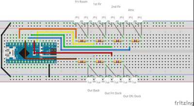
Need some help. As can be seen from code and description, 14 LEDs will be used, with two on each of seven pins. Assuming 18-20 mA each with a 470 ohm resistor per pair, this would exceed the 200 mA total for board. As I am anything but an electronic whiz, what would be the minimum resistor I would need to drop total amperage below that total?
AND would using PWM to reduce brightness also reduce the amperage or do I need to use higher ohm resistors anyway?
Photo Bud (aka John)
The Old Curmudgeon!
Need some help. As can be seen from code and description, 14 LEDs will be used, with two on each of seven pins. Assuming 18-20 mA each with a 470 ohm resistor per pair, this would exceed the 200 mA total for board. As I am anything but an electronic whiz, what would be the minimum resistor I would need to drop total amperage below that total?
AND would using PWM to reduce brightness also reduce the amperage or do I need to use higher ohm resistors anyway?
It's not recommended to use LED's in parallel with a single resistor, as due to inconsistencies in current draw, they won't all get the same current and will start to burn out, as one will hog more of the current - I have read about this in the past, and that is my recollection of it.
Wiring them up in series is recommended, that way they'll all get the same current going through them, but this also presents another problem... the voltage drop across the two LED's (the LED forward voltage * 2) may be greater than the 5V supply - You'll need to check the datasheet for your LED's.
Calculating the current using OHMS LAW is very simple - For example (2 LED's in series):
Resistance = (Supply Voltage - LED Forward Voltage * 2 LED's) / LED Current (in AMPS)
Resistance = (5 - (1.9 * 2)) / 0.015
Resistance = (5 - 3.8) / 0.015
Resistance = 1.2 / 0.015
Resistance = 80 ohms
Maybe looking at some cheap BJT's and a separate power supply is the way to go?
Cheers.
@frogandtoad Thanks, I appreciate the heads up AND Ohms Law info.
Photo Bud (aka John)
The Old Curmudgeon!
Photo Bud (aka John)
The Old Curmudgeon!
Except, of course, it doesn't work for pins 7, 2, and 4, since they are not PWM pins.
Photo Bud (aka John)
The Old Curmudgeon!
Photo Bud (aka John)
The Old Curmudgeon!
Have decided to keep two LEDs per pin and have also decided to modify code to use analogWrite so as to be able to dim to the degree desired using software, rather than resistors.
For reasons with respect to our previous discussion, I think this is a risky approach to take, and not something I would recommend.
[edit] - For reference, this might help: is-it-ok-to-put-leds-in-parallel?
By the way (programming tip)... there are some refactoring opportunities in your code, for example your 'for loop' could be implemented in a function, to make the code look a whole lot cleaner, so then you can just focus on program logic rather than traversing through clutter.
Less lines of code makes for a better coding and maintaining experience 🙂
Cheers.
By the way (programming tip)... there are some refactoring opportunities in your code, for example your 'for loop' could be implemented in a function, to make the code look a whole lot cleaner, so then you can just focus on program logic rather than traversing through clutter.
Less lines of code makes for a better coding and maintaining experience
I had a bit of time today, so thought I'd provide an example of what I meant by refactoring, and how it can help to clarify ones code, such that we can now focus on our design logic! if we implement the following function:
void flashLEDS(byte numIterations, byte numRooms, unsigned long duration = 250) {
    numIterations *= 2; // 50%/50% on/off

    for(int iterator(0); iterator < numIterations; iterator++) {

      for(int room(0); room < numRooms; room++) {
         digitalWrite(justRoomLEDs[room], (iterator % 2 == 0));
        }

      delay(duration);
     }
 }
...then we can simply incorporate it into our code as follows, and call it as many times (and anywhere), as we like:
flashLEDS(5, 6);
// Or..
flashLEDS(5, 6, 500); // Using custom delay
Hope this helps!
Cheers.
Hi John,
I have encountered this problem before of to0 many LEDs off of one board and reaching the boards power supply limit of 200ma. Even getting close to the limit can effect the boards functioning, a slight spike in power demand can cause a board power supply dip of a few milliseconds which causes the board to re-set. Your set-up would have continuous power from the pins when in use.
My solution was to find cheap suitable relay switches of latching mode. Their operation is from the pins, usually about 50ma or less, using a built in optocoupler, and the relay switches on the power to the LEDS, which can be many more than you are using. Just do not code the ON/OFFs for pins all at the same time. The drive power for the relay is also external, usually the same source as for the LEDs. The Arduino pin only activates to instigate the relay operation so is only live momentarily for a latching action, click ON click OFF for example.
Your code will need little change as the pins are already assigned to LEDs, and these will be wired to a relay instead.
One final comment, I agree that LEDs should have their own resistor, I put them at the relay end of the positive LED wire so there's only the led at the working end to fit where its required. There are loads of sites on the web where you can calculate a suitable value resistor for the voltage and LED being used.
Kimosubby
@frogandtoad - Thanks, I understood but the further clarification and example are great. I have gotten a little(?) sloppy over the years since my 40+ years of mainframe programming, analysis, and debugging experience. My only feeble defense is that I often write such code, then go back later to structure properly which is highly frowned upon in the C++ and variants world!
@kimosubby - In response to you and others, I've decided to go with separate resistors for each LED. From some of the other comments I've received, it appears that even with all LEDs on at the same time, I will still be well within power limitations especially if I use the PWM to limit brightness. First tests, not in structure, seem to indicate using PWM to limit power output to 25-50% will achieve the look I'm seeking.
About the worst that can happen is that it will fail sometime in my lifetime, which at 78 (in April), may not be all that long! lol If that happens, given the modularity of the design, it can be rectified by implementing other measures such as suggested by @kimosubby.
Photo Bud (aka John)
The Old Curmudgeon!
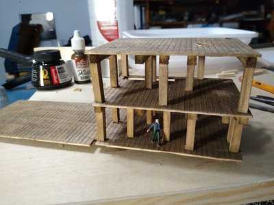
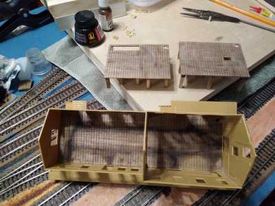
btw - Here is the modularity to which I referred. All components will have 2 mm JST-PH JST connectors.
Here is the multi-floor assembly that will be slide into (and be removable from) the one end of the building.
And here, again, is the building into which it fits.
Photo Bud (aka John)
The Old Curmudgeon!
I am still new to Arduino, but I 'm familiar with c++. I have a related question. I'm not sure if this should be a new topic or for another forum, but my queries concern timing. I am building something very similar. Would his code be more effective with millis? When would you use millis vs. chrono?
Thanks in advance 🖖🏾
LAW
@wells5150 - I'm still a noob with all of this, but from what I just looked up, "chrono" is not found in Arduino programming language. There doesn't seem to be any native time functions, thus the need for using "millis".
Photo Bud (aka John)
The Old Curmudgeon!


