You wrote "Depending on how you make the frame to hold the sprockets, it may take a wider than 4" pipe".
Yes quite a bit wider and once I get that wide the ultrasonic just might work.
I think you know I've got my test kit and working through a work flows so will be busy for awhile.
And just for grins, if nothing else, I am going to shoot that HC-SR04 down a 4"pipe. I just recently watched a YouTube video where a guy used the HC-SR04 to monitor water in a 9" (23 cm) diameter tank and briefly mentioned that the minimum diameter for the HC-SR04 was 3.5" (9 cm). Don't know where he got that specification. Also his tank with the 9" (23 cm) diameter was somewhere around 36" (91 cm) deep and mine is 48" (122 cm) deep. So I feel pretty strongly that the deeper the tank the wider the diameter needs to be. Sad thing is I lost track of the video but do remember the details and will be able to figure out a few things on my own.
I also saw yet another video that took something like 20 readings, dropped ones that were materially high and low and then averaged the remaining. Got some consistent super accurate measurements at 5 & 6 cm and 20 cm. BUT for whatever reason at 10 cm it was really off, I mean it was reading something like 17-18 cm. I am going all the way to 122 cm. So I've got some playing around to do and will keep you posted.
Lots of learning going on here even if I've not put anything together yet, fun too!
Its midnight here in Colorado but I started to think I was procrastinating on doing some kind of a test on the 4" PVC. So I decided to do a Q&D(Quick & Dirty) and stand the 4" PVC on the floor, use some supplied code and simply hold the HC-SR04 in my hand. Once inside the 4" PVC for several measurements and once outside for several measurements. I felt that by doing this if being inside the 4" PVC materially affected things it would show up.
For a hand held situation the inside and outside measurements were the same that being between 97 cm 38.1" & 99 cm 38.9". Now 40.25" is 102 cm, so this is about 3" 7.6 cm short, but hand held don't know.
So I did another test with the HC-SR04 sitting on my desk pointing at a wall 48" 122 cm away. Here the HC-SR04 consistently returned 105 41.3" & 41.7" 106 cm. so this is 6" 15cm short.
For the above tests there was NO consideration for temperature & humidity.
The main thing from these tests is that I need to go further. This would be a great situation having the HC-SR04 outside the tank in the measuring stack since it would be one device instead of several as required by the “XKC-Y25-NPN Non-Contact Liquid Level Sensor” approach.
Yes I am still liking the “XKC-Y25-NPN Non-Contact Liquid Level Sensor” because of its likely dead on accuracy. And so I will have to determine that the HC-SR04 will return reasonable consistent measurements. For sure will need to implement a humidity and temperature measuring device.
Update on previous test/post: As I went to shut things down and go to bed I noticed that the set up on my desk 48" from wall might be partially picking up a window drape. So I moved it to a position less likely affected by the drape and now it is consistently returning 117 cm 46.o", 118 cm 46.4" and a few 119 cm 46.8". Before it was 6" off now it is about 2" off and this better aligns with the tests for the 40.25" 4" PVC.
Those tests look encouraging. I wonder if LIDR range sensors would also work. I think you could then use a smaller tube as it produces a much narrower light beam instead of an ever increasing sound wave. You would probably have to put in a floating disk in the tube otherwise the lazer would possibly penetrate the water instead of bouncing back.
I expect you saw the dronebotworkshop video that compares the TOF10120 v HC-SR04. I expect the TOF10120 could be constantly calibrated if used inside a tube and may not be effect by temperature or humidity. (Just a thought and I have not actually used the TOF10120 in this context so this expectation may be well off the mark)
Bryon yes I've seen the dronebotworkshop video that compares the TOF10120 v HC-SR04. And, laser has been under consideration.
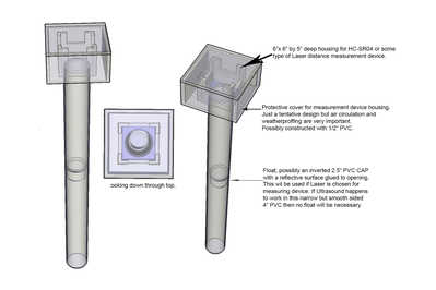
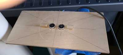
Here are a couple images from a previous post where I designed a float inside the 4" Measurement Stack to deal with Laser. The float is a 2" PVC cap inverted with a reflective surface glued to close opening and face up.
Ultrasonic v Laser: one advantage of Ultrasonic is nothing inside the Measurement Stack and so one less moving part. Moving parts are not the most desirable thing to use, what if the float gets jammed for one reason or another?
As to LIDR, I am not yet real sure what the difference is between Laser and LIDR. Did a bit of digging here but still not real sure, first analysis leaves me thinking that LIDR has a wider beam than Laser. The dronebotworkshop you referred to was Laser, not LIDR.
I've seen somewhere that the differences between Ultrasonic and Laser beam spread is something like 45 degrees vs 30 degrees respectively. Not sure the values are correct but I do recall about a 15 degree difference. I may be testing both and anxious to see which, if either, proves more accurate through all measurements up through 48".
Another technology I've explored and not yet mentioned in this thread is a Capacitance Sensor. Briefly said "Capacitive Sensors work exploiting the variation of the dielectric coefficient when the water (or other liquid) raises and occupies the space between the two sensor's plates that constitute the capacitor." NOW be absolutely sure I do not know enough about electronics to spit out that last sentence, it was copied verbatim from the following YouTube video that not only explains Capacitive Sensors but shows how to build one.
These Capacitive Sensors can be VERY accurate and the two cons for them are:
1) Building it might be tricky, especially for something to go the long haul.
2) Not sure how it will hold up in dirty water for years and years.
A big plus for the Ultrasonic Sensor is it sits on top of the Measurement Stack with NOTHING invasive as both the Laser and Capacitive Sensors have and so make for a relatively simpler replacement.
As to the float for the Laser Sensor, I am not real concerned about it being problematic and so if more accurate than the Ultrasonic it would be a strong candidate. Also the Laser is more weatherproof than the HC-SR04 but then there are weatherproof Ultrasonic sensors that may or may not work in the 4" Measurement Stack.
LIDR not sure if it fits into my system?
To conclude: ALL approaches are still open: accuracy, dependability, ease of implementation, ease of maintenance and cost are significant evaluation factors.
Another technology I've explored and not yet mentioned in this thread is a Capacitance Sensor. Briefly said "Capacitive Sensors work exploiting the variation of the dielectric coefficient when the water (or other liquid) raises and occupies the space between the two sensor's plates that constitute the capacitor." NOW be absolutely sure I do not know enough about electronics to spit out that last sentence, it was copied verbatim from the following YouTube video that not only explains Capacitive Sensors but shows how to build one.
These Capacitive Sensors can be VERY accurate and the two cons for them are:
1) Building it might be tricky, especially for something to go the long haul.
2) Not sure how it will hold up in dirty water for years and years.
I thought they were just for consistent conditions, steady temperatures and homogeneous fluids.
If it's using the water as the dialectic, then surely water quality would be a huge factor in both sensitivity and reliability. You'd think that many possible contaminants in both city and irrigation water could skew the result.
Changes in temperature would also affect the readings.
Can you do some pH tests on your city and irrigation water easily to see if there's much difference between them ?
Anything seems possible when you don't know what you're talking about.
The dronebotworkshop you referred to was Laser, not LIDR.
Ah yes, it was a Laser. You have probably also seen the dronebot video on LIDAR. It seems it works on IR light. So I guess thats yet another possible sensor to consider. In fact these seems to quite a few distance sensors to choose, although all variations of the same core technologies.
https://www.sparkfun.com/categories/84 This shows a page load sparkfun distance sensors.
For a float in a smaller pipe maybe a pingpong ball would make a good float that should resist getting stuck.
But as our sage @dronebot-workshop indicates in his comparison video, it may be best to use more than one technology. This would provide a bit of backup in critical applications.
Posted By: @will
If it's using the water as the dialectic, then surely water quality would be a huge factor in both sensitivity and reliability. You'd think that many possible contaminants in both city and irrigation water could skew the result.
Changes in temperature would also affect the readings.
Can you do some pH tests on your city and irrigation water easily to see if there's much difference between them ?
Will thanks for the heads up and if I get into a more serious evaluation of the "Capacitance Fluid Level Sensor" it should not be a big deal get a pH meter and check that out. Also in my somewhat limited research, but still some significant time spent, of "Capacitance Fluid Level Sensors" I believe they can be used for many fluid types, both conductive and non conductive. Also the design differs when fluid is in either a non conductive (plastic etc.) or conductive (metals) tank.
Posted By: Will
I thought they were just for consistent conditions, steady temperatures and homogeneous fluids.
Note that I used "Capacitance Fluid Level Sensor" above instead of "Capacitance Sensor" and will do so in the future because there are many different uses of capacitance in measuring.
Posted by: @byron
You have probably also seen the dronebot video on LIDAR. It seems it works on IR light.
Yes I did at one point start to watch the dronebot video "Getting Started with LIDAR" and at about 7:30 in the video there were images of airplanes using the technology to do all sorts of things like what Google Earth publishes. So being as busy as I am wrote this off as being something not applicable to my project.
But thanks to your heads up the "TF Mini LIDAR", or other ones like it, are possible solutions. It just might be more accurate and better weatherproof than the HC-SR04. Also the installation effort is the same as Ultrasonic and Laser.
Although the price seems higher sometimes "Penny conscious and Dollar poor" is a good thing to keep in mind.
A significant consideration is the LIDAR's (and I think Laser too) minimum range (30cm) as compared to the HC-SR04 (I think about 3-4 Cm). But this can be resolved by making my "Measurement Stack" rise above the storage tanks. Not sure if the extra depth will have an effect but will for sure test before going too far.
Posted by: Byron
In fact these seems to quite a few distance sensors to choose, although all variations of the same core technologies.
I would just like to take a moment and try to separate some core technologies, at least the way I've been seeing them. Most distance sensors like Laser, LIDAR and Ultrasonic rely on Time of Flight (TOF).
In this thread we are also looking at sensors that don't use TOF, like the Capacitance Fluid Level Sensor, the Hall Effect Sensor and XKC-Y25-NPN Non-Contact Liquid Level Sensor.
There are also other ways to determine the level of something in a tank, for example: water pressure at bottom of a tank, some devices dropped into a tank and various float arrangements.
Posted by: Byron
You would probably have to put in a floating disk in the tube otherwise the lazer would possibly penetrate the water instead of bouncing back.
For a float in a smaller pipe maybe a pingpong ball would make a good float that should resist getting stuck.
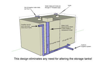
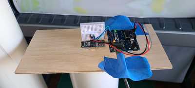
Spent a few hours yesterday at the Home-Depot plumbing section. I am going to put together my "Measuring Stack" in a way that everything in the way of electronic components and software can developed and thoroughly tested independent of the two 275 gal IBC tanks that are already installed in my yard. Felling I've got this process/configuration figured out, just need to put it together. This way I will be able to work on the system through the winter in my heated workshop.
While at Home-Depot I also figured out my float. It will be a pipe cap that fits a bit loosely inside 4" Measuring Stack with likely a piece of metal closing it and making it buoyant. The metal cover that will be custom cut to float freely will give me a way to extract the float, if needed, with a magnet attached to something.
So yes the laser will need something to bounce off of and now I am thinking even the Ultrasonic and LIDAR will perform better with a hard surface to bounce off.
Posted by: Byron
But as our sage @dronebot-workshop indicates in his comparison video, it may be best to use more than one technology. This would provide a bit of backup in critical application
Yes and I have been thinking it might be worthwhile to use a couple sensors and then develop programming that has one check on the other. To say the least this could get complicated and introduce hard to find bugs. This gets back to the "Penny conscious and Dollar poor" thing. I am getting more and more committed to finding a rock solid way to measure and the most rock solid to date is "XKC-Y25-NPN Non-Contact Liquid Level Sensor".
Posted by: Byron
https://www.sparkfun.com/categories/84 /a> This shows a page load sparkfun distance sensors.
THANK YOU, THANK YOU, THANK YOU for this link. Lots to look at and consider. Nuff said for now!
Update on HC-SR04 measurements in 4" PVC
Being concerned with some video's having mostly accurate measurements but some off the charts I refined my testing environment and tried several measurements through the range I will be expecting to use. I stretched it some doing one out to 80" 203 Cm. To say the least I am very pleased with the results, no off the chart results. And they are off a wee bit and have not yet got a proper humidity and temperature sensor.
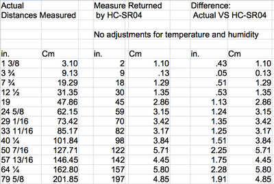
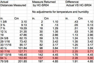
Here is a spreadsheet of the tests.
With all this I am super confident that the 4" Measuring stack is not altering measurements. For every test I did it both in and out of the stack and measurements were always the same within a Cm.
For anyone interested the following describes how tests were performed.
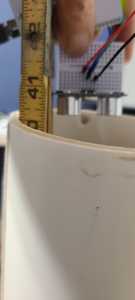
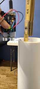
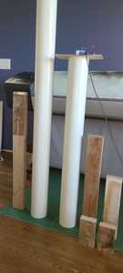
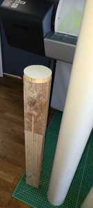
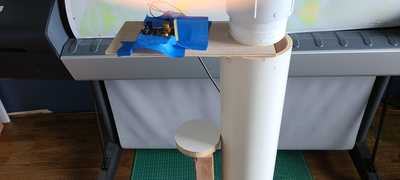
I started with a 80" and 40" length of 4" PVC with misc lengths of 2x4's intended to be stacked on top of one another with a simulated float on top. The float is a round piece of coated MDF about 1/4" smaller than diameter of inside of PVC. For each measurement I would stack up 2x4's to get a desired height and place the float on top. I would then take a measurement to top of PVC with a ruler, next use the HC-SR04 to take a measurement outside the PVC and then place the 2x4 stack inside the PVC. Actually I lifted the PVC over the stack. I would then use HC-SR04 to take a measurement inside the PVC.
Excellent news. Thank you so much for showing the 4" tube results, surprising what that extra inch of diameter can do.
The error looks to be quite linear, so you could probably improve the results just by adding in a scaled error correction value too.
How accurate do you need your results to be , I don't think that's been covered so far.
I'm also curious about whether the float is really required or if the water surface itself would provide enough reflection for the sound pulse.
You've done an impressive amount of research, I hope you'll find making a final decision easy 🙂
Anything seems possible when you don't know what you're talking about.
That an encouraging set of test results. I suspect that consistency is actually more important than absolute accuracy (i.e. the low mark on your tank always reports the same distance value even if its not an absolute cm value. Though, come to think of it, probably even an inconstant reading of + - a centimetre may not matter too much, at least in the way I envision it working.
I see you are thinking of some sort of compensation for the readings based on temperature and humidity. Beware of some of those cheapo temp and humidity sensors as I have found they can report values outside of their spec. I once rigged up a test of a number of temperature sensors and they all reported different values, the best ones within their spec of 0.2 degrees, but some had over 2 degree difference, so one or another must have been outside its spec. For accuracy I would steer clear of those DHT sensors as they proved to be the most inconsistent in my test, though they may have all been some cheapo Chinese ones.
But I do wonder if the measurements of the ultrasound sensor in a consistent and relatively short measurement range would be much affected by temperature and humidity as it will be placed in a consistently humid environment anyway, but it will be interesting to see what your testing shows.
I'm thinking that Laser, LIDAR, or RADAR sensors would not be affected by humidity and temperature to the point where it would effect the measurements in a tube plus they could be put into a much smaller diameter tube. However this is not based on any real experience or testing of these sensors.
Thanks for reporting your results you sure are powering along with your project.
Thanks guys for your responses and yes consistency is more important than accuracy since adjustments can be handled in coding. I was excited yesterday and still excited by the fact the 4" Measurement Stack proved viable beyond any doubt.
I am still concerned with the HC-SR04's sometimes unexplained off the charts measurements in the middle of perfectly accurate measurements. I observed this in a couple videos including one of Bill's. One observation was between other valid measurements and the observation in Bill's was just for measurements further away and it was overlooked based on the possibility of other stuff interfering. And, I was playing with some tests last evening and one happen to me, not for a real far off measurement but an intermediate value.
With all this I pondered Bill's situation for farther off measurements and overlooked because of the possibility of other stuff interfering. What came to mind was my stack validity verification measurements on the 80" stack that were outside the stack. My studio has lots of stuff in it and none of the 13 measurements were effected.
And with this pondering I took a closer look at the chart I published yesterday and there are a couple lines that did not follow the consistent linear pattern most measurements followed. I have the concerning lines marked in red.
Really starting to think that for the HC-SR04 to be considered dependable will require two devices checking on one another. After all this is not a "play with system" I am developing, it is going to have to work when I am on extended vacation.
I do think there is concern over temperature since ranges will be large, between 0C(32F) and 43.3C(110F). If I get a chance will produce some type of graph showing different measurements based on temperature and various distances. Humidity will likely be high but consistent.
Posted by: Will
I'm also curious about whether the float is really required or if the water surface itself would provide enough reflection for the sound pulse.
For sure with Ultrasound the float will not be required but it might help since water is a great conductor of sound and who knows what the effects will be.
Posted By: Byron
I see you are thinking of some sort of compensation for the readings based on temperature and humidity. Beware of some of those cheapo temp and humidity sensors as I have found they can report values outside of their spec.
I ordered the one that Bill used in his video on improving measurements by considering temperature and humidity.
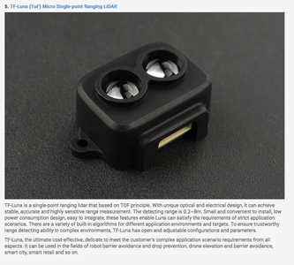
Finally, so you guys know I am feeling real strong that with all that is at stake here I would be remiss not trying LiDAR and so ordered the following:
It's likely not the best, only $25 at Amazon but with 23 great reviews. Used Amazon because of free delivery and if it don't look like it is dependable enough I can send it back free of charge with no hassle. Noteworthy I think it is titled in part as "Single Point Ranging". I am guessing from this there are different flavors of LiDAR. Any thoughts?
Hi @wamagee,
Interesting project which I have been pondering.
I am thinking about the ultrasound method, although the test might be worthwhile with any technique, since it might give advance warning of an 'unexpected' problem.
I wondered, if particular water height values that you mark as having larger errors corresponded to resonance positions ... like an organ pipe. This could mean specific heights would read incorrectly.
You have already done a good manual test to check the general calibration, so my suggestion is to look for 'strange' errors that only appear at specific heights, hence supplementing your first data.
---------
Set up your eqipment as before, but this time introduce a slow 'leak' .. so that it takes maybe an hour to empty the tube.
And get the measurement system to record the height on a frequent basis .. say once per second. As you have already 'calibrated' a number of specific heights, it shouldn't be necessary to repeat the manual measurements.
So then you might get a series of say 3000 readings. At this point, graphing measured height versus time, using a spreadsheet, should show a nice steady progression .. if you get peaks and troughs then these will be a guide as to the uncertainity in any one measurement due to 'resonance'.
If there are specific peaks and troughs, these could be troublesome if you have an automatic fill/supply system, so knowing about them would help with refining the control system to make allowance.
Of course, in the field, there may be other factors which add further errors.
NB I am confused by your chart of values ... apologies if it just me being thick, or maybe I misunderstood the headings, but you might like to check the calculations. e.g. top line:
Actual Distance:          1 3/8" = 1.375"  ; 1.375 X 2.54 = 3.4925 ;  ~3.49 cm


Measured Distance:  2"    ;     2 x 2.54 = 5.08 cm


Difference:        2 - 1 3/8  =  5/8"  = 0.625" ;   0.625 X 2.54 = 1.5875 cm  ;

                      5.08 - 3.4925 = 1.5875 cm ;   ~1.59 cm
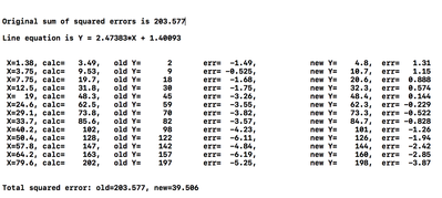
Just for fun, I tried deriving an equation loosely based on least square error (That is, I had to reverse the sign on the intercept). The result was ...
The columns are: X = your measurement in inches; calc = X*2.54 to get cm; old Y = your NC-SR04 observation; (first) err = error between calc and old Y; newY = calculated value from line equation; (second) err = error between calc and line equation value.
The total squared errors at the bottom are the summed squares of the two error columns.
Hope this is of interest to you.
Anything seems possible when you don't know what you're talking about.

