Jay,
one thing that I want to mention is, that I want to use rotary pulse encoders in spite of potentiometers, because they are more precise and have a longer lifespan (in theory).
They should be programmed as easy, as potentiometers with the arduino. The only inconvenient is, that they need a defined zero point. I will, most probably, use a light barrier or a magnetic sensor. At the moment, I dont know exactly what. Application will be on the pedals and yoke, as well on the tiller. Later on on the quadrant. But I will work on this, only after wiring up the panel lightning.
You see, there are a lot of things to do.
Stay safe,
Peter
Hi, Peter.
You might want to consider using string potentiometers for determining position. I find them to be very sturdy and reliable.
I had the idea of using aviation-grade steel cables for my TQ reels (3). This is to provide a natural tension to the thrust levers without having to engage the friction lever all the time, which is very unrealistic in feel. These are in a continuous loop, running through each of three (3) rollers mounted to the wooden ‘floor’ of the TQ. I am running a smaller cable to each reel which will be connected to a string potentiometer for each engine’s control. String pots are very easy to read and calibrate through interfacing. You set the zero position and from there, can delineate positive and negative (direction) values for the application. I had two (2) reels set-up previously this way and they worked perfectly…I was very pleased…right up to the point where I accidentally dropped a heavy crimping tool on the floor and it cracked! I’ll draw a diagram later and post it here to give you a better idea of what I’m doing. I have steel ball/cable shank balls attached to both ends of each main cable, attached to the recesses on each TQ reel. Time-consuming, yes, but it paid-off because of its simplicity and operation.
I will do something similar for the flaps handle. The trim position indicators will probably be servo/stepper-driven.
More later.
Jay
Hi Jay,
I am very interested in your approach. If possible let me see more.
I dond´t have enough space in my “(home) office to put everything together in a cockpit shell. therefore I mounted every unit as indepent module on aluminium profile bars with wheels, as you can see under the captain´s chair, the RT-box and the quadrant / pedestal.
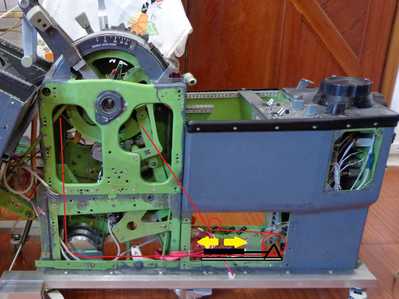
Therefore I have not much space under the quadrant, as you have with the wooden base. I show you my 1st approach, but I will modify it in the near future. Therefore any alternative idea, as your approach, is highly appreciated.
Until next.
Peter
Still loving your components!!
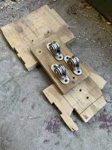
Here are two (2j photos taken a little while ago. It’s the ‘floor’ of my TQ and the 2nd piece of wood is where the rollers are attached. I had to stagger them due to size constraints; the mounting is too wide to place in-a-row. Nevertheless, it worked great.
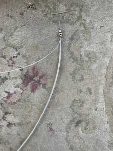
The second photo is the aviation-grade steel cable and ball shank connection. The smaller cable willbe attached to the string potentiometers. That’s the current plan.
Interesting approach, Jay.
I will have to modify my project, because actually I am blocking the movement of the CG indicators.
Many thanks for your hints.
Stay safe.
Peter
Hello Jay,
I mentioned that I will have to modify my quadrant / pedestal project, because actually I am blocking the movement of the CG indicators. I show you a picture what I pretend to do: I will lengthen the steel cables and mount the right pulley (3 pcs.) on 3 single rails attached to 3 single gas springs, to achieve mechanical tensioning to the steel cables.
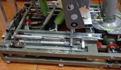
You can see, that I used a similar mechanism on the pedals / column unit. The gas springs are far much better than normal springs.
There is a lot of work to do!
Stay safe!
Peter
IMPORTANT MESSAGE:
Dear Jay,
dear followers!
I want to follow Bill´s suggestion to start a new thread, instead of keeping it in the "Introduce Yourself" section, as it will be easier to reference it later. A great place to put this is the "Show & Tell" section in the "Project Corner".
I created the topic "BOEING 727-200 HOMECOCKPIT with original aircraft parts and instruments".
Therefore I want to discontinue the discussion in the "Introduce Yourself" section and continue in the "Show & Tell" section in the "Project Corner".
PLEASE USE THIS THREAD TO CONTINUE DISCUSSING THIS ISSUE.
At this point, I want to remenber, that I have two other threads on the ARDUINO Forum: SYNCHROS "SELSYNS" as Output Devices and SYNCHROS ”SELSYNS” as Input Devices.
Many thanks for your attention.
Peter


