hello everyone
i am trying to create a Dc motor controlling circuit
3.7 V motor & it takes 25mili amps to run at full speed,
i want it to be turned on with one push button
first push( motor speed should be 1/3rd of the full speed)
second push( motor speed 1/2 of the full speed)
3rd push ( full speed).& by pushing the same button 4rth time it should be turned off
i have no clue where to begin with this circuit
any help regarding this will be much appreciated
thank you
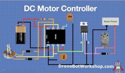
@najam-ali99 Please re-post this in the appropriate forum and/or sub-forum as a new topic. But you may want to look at Bill's videos (DroneBotWorkshop on YouTube) about DC motors in the meanwhile.
First computer 1959. Retired from my own computer company 2004.
Hardware - Expert in 1401, and 360, fairly knowledge in PC plus numerous MPU's and MCU's
Major Languages - Machine language, 360 Macro Assembler, Intel Assembler, PL/I and PL1, Pascal, Basic, C plus numerous job control and scripting languages.
My personal scorecard is now 1 PC hardware fix (circa 1982), 1 open source fix (at age 82), and 2 zero day bugs in a major OS.
Welcome to the forum.
As a start you'll need the motor, a suitable power supply, a pushbutton, a motor controller module and a microcontroller. You'll need to decide what size and characteristics of each depending on the exact details of your project. Only you can determine what those needs are since only you know what you have in mind.
As an addendum, I would suggest that you also include a toggle or slide switch as an on/off connected between the power source and your circuit so that you can shut the whole operation down while you're in the design and development (and especially testing) phase. You won't want to have to tear out the wiring if your project won't stop or change speed on demand.
Anything seems possible when you don't know what you're talking about.
The speed controlling behaviour would be easy to implement in software using an Arduino board and PWM output but would using an Arduino board be a too large for the project? Essentially you increment a speed variable each time the button is pressed and on the fourth press reset the speed variable value to zero.
It could probably also be done in hardware alone using a 555 IC and a counter IC. The reason for the 555 is to generate pulses for PWM control which gives the motor maximum torque at lower speeds. The counter IC would select the resistor value on each press (replacing a variable resistance controller)
This might be a good test question to ask Chatgpt, anyone?
How to make a circuit to control the speed of a low voltage motor using one button.
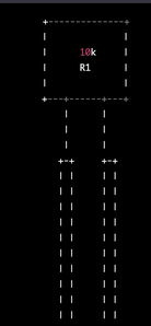
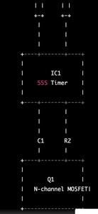
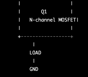
@robotbuilder Ok, I tried it, here is the diagram. You will need to fix the spacing, I did a little bit but not going to waste my time on this.
+--------------+
| |
| 10k |
| R1 |
| |
+---+------+---+
| |
| |
| |
+-+ +-+
| | | |
| | | |
| | | |
| | | |
| | | |
| | | |
| | | |
| | | |
| | | |
| | | |
| | | |
+-+ +-+
| |
| |
| |
+----+-------+----+
| |
| IC1 |
| 555 Timer |
| |
+----+-------+----+
| |
| |
| |
C1 R2
| |
+----+-------+----+
| |
| Q1 |
| N-channel MOSFET|
| |
+-----------------+
|
LOAD
|
GND
And here is what it said.
Here's how the circuit works:
-
Pressing the button triggers the 555 timer (IC1) to generate a square wave signal at a frequency determined by R1 and C1. The output of the 555 timer is connected to the gate of the MOSFET (Q1) through a resistor (R2).
-
The duty cycle of the square wave signal can be controlled by adjusting the value of R1 or C1. The longer the ON time of the square wave signal, the higher the motor speed. The shorter the ON time, the lower the motor speed.
-
The MOSFET (Q1) acts as a switch that controls the power supplied to the motor. When the gate of the MOSFET is driven high by the square wave signal, the MOSFET turns ON and allows current to flow from the power supply to the motor. When the gate is driven low, the MOSFET turns OFF and the motor stops.
-
The motor speed can be adjusted by varying the ON time of the square wave signal using the single button. Each time the button is pressed, the ON time of the square wave signal increases or decreases, causing the motor speed to increase or decrease accordingly.
Note that this circuit is designed to work with a low voltage motor and may need to be modified if you are using a higher voltage motor. Also, it's important to use a suitable heat sink for the MOSFET to prevent overheating.
First computer 1959. Retired from my own computer company 2004.
Hardware - Expert in 1401, and 360, fairly knowledge in PC plus numerous MPU's and MCU's
Major Languages - Machine language, 360 Macro Assembler, Intel Assembler, PL/I and PL1, Pascal, Basic, C plus numerous job control and scripting languages.
My personal scorecard is now 1 PC hardware fix (circa 1982), 1 open source fix (at age 82), and 2 zero day bugs in a major OS.
It clearly failed to answer the question which involved using one button to control the speed.
However if it doesn't interest you with regards to Chatgpt then by all means don't waste your time with it.
@robotbuilder I think it did answer
The motor speed can be adjusted by varying the ON time of the square wave signal using the single button. Each time the button is pressed, the ON time of the square wave signal increases or decreases, causing the motor speed to increase or decrease accordingly.
It does interest me, but why should I spend time fixing the drawing when everyone else can plug in the question and get their own drawing?
I am a little disappointed with the quality of the drawing though.
I added some screen grabs as well.
First computer 1959. Retired from my own computer company 2004.
Hardware - Expert in 1401, and 360, fairly knowledge in PC plus numerous MPU's and MCU's
Major Languages - Machine language, 360 Macro Assembler, Intel Assembler, PL/I and PL1, Pascal, Basic, C plus numerous job control and scripting languages.
My personal scorecard is now 1 PC hardware fix (circa 1982), 1 open source fix (at age 82), and 2 zero day bugs in a major OS.
It didn't answer it for me despite its claim. I couldn't really figure out from the ascii circuit where the button was let alone how it would change the on time of the square wave. The answer made no sense to me at all with regards to how to build it or how it actually worked it simply made the claim. I won't waste my time with how it didn't answer the question but if anyone can redo that ascii circuit as a proper circuit diagram then perhaps, if the answer isn't nonsense, it can be explained. I couldn't convert the ascii circuit into any meaningful properly drawn version or the circuit.
Now if you had some suitable resistor values you might select one at a time with the press of a button that incremented a counter to change which one was selected to replace the variable resistor normally employed in versions of a 555 based motor speed control circuit.
https://dronebotworkshop.com/555-timer/
@robotbuilder Agreed, but TBH, I didn't know AI was even supposed to be able to create electronic circuits. I can understand AI mastering all the writing skills and even doing a half-decent job at software creation but hardware is much more difficult, especially with such a shall we say loose circuit description.
First computer 1959. Retired from my own computer company 2004.
Hardware - Expert in 1401, and 360, fairly knowledge in PC plus numerous MPU's and MCU's
Major Languages - Machine language, 360 Macro Assembler, Intel Assembler, PL/I and PL1, Pascal, Basic, C plus numerous job control and scripting languages.
My personal scorecard is now 1 PC hardware fix (circa 1982), 1 open source fix (at age 82), and 2 zero day bugs in a major OS.
Well I gave a verbal solution using a 555 and an ic counter and maybe an analog switch. I wouldn't draw up a solution myself without building it to to see if it worked. I couldn't find a solution on the internet but I know there are electronic devices that you turn on with one press of a button and with each press the motor goes faster until the last press it turns off.
There are however software solutions a plenty online showing how to use the Arduino board to produce the desired behavior that was not picked up by Chatgpt.
@robotbuilder With regards to your last paragraph, if ChatGPT was not trained with that particular data then it's highly unlikely it can generate an answer like that. Maybe Bill will do a video on how ChatGPT was trained and with what data, that might help folks understand what is happening and what will happen as we go forward.
This link is a very good explainer HERE
First computer 1959. Retired from my own computer company 2004.
Hardware - Expert in 1401, and 360, fairly knowledge in PC plus numerous MPU's and MCU's
Major Languages - Machine language, 360 Macro Assembler, Intel Assembler, PL/I and PL1, Pascal, Basic, C plus numerous job control and scripting languages.
My personal scorecard is now 1 PC hardware fix (circa 1982), 1 open source fix (at age 82), and 2 zero day bugs in a major OS.
@zander i am sorry if any inconvenience might have caused , i am new to the forum & trying my best to learn about it.
@zander thank you ron
i will post it there too & i have tried all the youtube videos, none of them are useful in this particular circuit, i have tried mosfet with 555 timer but concept of switching between different speeds with one switch is still uncovered
- thank you sir for sharing that information,
- i have tried all youtube videos but none of them works for this particular circuit
- it will be a piece of cake for a pro person to replace a variable resistor with a push button but for a beginner like me it might take a month or more to understand the concept of it.
- thanks once again for sparing your precious time for my post
- many thanks @ robot builer
Here is a sample sketch to drive the motor using the button as you described. This probably won't work as you intend as it drives the motor directly via PWM which would require an extremely wimpy motor. It can be adapted however to drive a suitable MOSFET which, in turn, will drive a suitable.
This sketch comes clean but is otherwise untested.
/**************************************************************************/
//    Example sketch for question posed in DBWS
//
//    Assumes:
//        - motor draws very little power (else use pin to drive MOSFET)
//        - button on pin 4
//        - PWM to drive motor on pin 3
//        - suppress button presses occurring inside 100 ms of each other
//        - motor speeds are: off, 1/3, 1/2 and full power as per posing
//
//    By Will Feb 18 2023
/**************************************************************************/
//
//    Declare variables used for timing
//
unsigned long   lastTime=0;                 // Time of last button push
unsigned long   debounceTime = 100;         // Allow 100 ms beween button pushes
//
//    Declare pins used
//
const byte  buttonPin = 4;                  // Button will be tied HIGH in pin mode
const byte  PWMPin = 3;                     // Motor driven here (must be PWM pin)
//
//    Declare PWM states and speed values (off, 1/3, 1/2 and full)
//
int   PWMState, PWMoff=0, PWMlo=85, PWMmid=127, PWMhi = 255;
//
//    Initialize values and states as required
//
void setup() {
  pinMode(buttonPin,INPUT_PULLUP);          // Button pulled HIGH via internal resistor
  pinMode(PWMPin,OUTPUT);                   // PWM will be controlled from here
  PWMState = PWMoff;                        // Always starts OFF
  analogWrite(PWMPin,PWMState);             // Force PWM pin low
}

void loop() {
  if (digitalRead(buttonPin)==LOW && (millis()-lastTime > debounceTime) ) {
    //
    //    User has pushed the button and at least 100 ms has passed since last push
    //
    if (PWMState==PWMoff) {                 // If motor was off
      PWMState =PWMlo;                      // Turn it on low
    } else if (PWMState==PWMlo) {           // If motor was low
      PWMState =PWMmid;                     // Turn it on mid-range
    } else if (PWMState==PWMmid) {          // If motor was mid-range
      PWMState =PWMhi;                      // Turn it on full speed
    } else {                                // If motor was full speed
      PWMState =PWMoff;                     // Turn it off
    }
    //
    analogWrite(PWMPin,PWMState);           // Set new motor speed
  }
}
Anything seems possible when you don't know what you're talking about.


