I'm currently using an IR receiver to wake a sleeping Arduino Uno (or Nano) and to also put it back to sleep. It seems to work ok, but are there any other/better options? One problem I seem to have is that some kind of local interference is causing a false trigger on the IR receiver.
Thanks
Hi @yurkshirelad,
Assuming a simple switch is inconveneint ... Are you just taking the presence of an IR beam as the cue to wake up or sleep?
All electromagnetic radiations (light.. radio..) suffer from stray bursts from time to time, so simply using (say) a radio transmission, without examining it carefully, is liable to suffer the same problem.
Could you make the IR transmit a pattern, for say 1 second ... and the receiving device look for the pattern ... then, if the received pattern doesn't match expectations, it is a false alarm, and it should return to its previous state?
Of course a bit black tubing or similar to shield the IR detector from all but a direct beam might reduce the incidence of false signals. Also, maybe reduce sensitivity of detector?
And have you checked it is actually detecting an IR beam ...electrical noise in the photodiode amplifier area could result in a pulse. Simple test .. ensure it never wakes up/goes to sleep with a bit cardboard/tape over the photodiode?
Best wishes, Dave
Thanks Dave,
The IR receiver outputs active high, so the Uno is waking on a falling edge on its input pin. There does seem to be some ripple on the receiver's output so perhaps it's enough to wake microcontroller. I can't remember if the input pin was configured with INPUT or INPUT_PULLUP. I'll try a bit of tape as you suggested.
Hi @yurkshirelad,
I don't know which receiver you using .. so I took a look at adafruit, who showed TSOP38238 ....
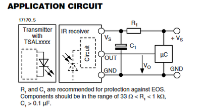
https://www.adafruit.com/product/157 and following up the datasheet link, finding...
I noticed the suggestion of an RC filter on the power supply.
Of course, you may have a different device or this device, with filtering, but hoped you wouldn't mind me making sure.
Best wishes, Dave
Thanks Dave,
I think it's the Elegoo IR receiver from their starter kit, so perhaps it's this one - https://www.instructables.com/Basic-Infrared-Receiver-Tutorial/. It looks like there may be a pull up resistor on the receiver's output on this tutorial, if I'm reading the diagram correctly.
I don't know what the actual IR receiver component is (without the DEV board) but I'll try to google it. Actually, I may still have Elegoo's documentation somewhere for the kit.
Elegoo's documentation doesn't show a pull resistor or the component's model number.
I put a 10k pull up resistor on the input pin so I'll see if it makes a difference.
Hi @yurkshirelad,
I think we are on the right lines ... albeit, the device is probably a clone of a clone, which may have mutated a little as different manufacturers have approximately copied each other, to grab a share of the remote control market.
I found two different "Elegoo Mega M3 Project" starter kit manuals on the web, the first at https://www.manualslib.com/manual/1353374/Elegoo-Mega2560.html
and the second as part of the software download on the Elegoo site
They refer to different devices ...PNA4602M and AX-1838HS, the first is apparently a Panasonic part,for which I found a data sheet on the web, the second is described in the Elegoo manual. I haven't looked at these sheets in detail, which differ in style and amount of content, but the immediate reaction is that their specs are describing devices similar to each other, and also the Vishay device I previously found a link to on the Adafruit site. Although the devices have cosmetic differences, my guess is they aim to direct replacements for each other, and good advice on one datasheet, maybe a good hint for the other variants as well.
They all show a similar block diagram of the internals of the device, including common emitter output stage, with two showing a nominal values of 20kOhm and 30kOhm respectively for the internal collector load resistor.
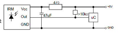
I included the Vishay application circuit suggestion previously; the AX-1838HS equivalent is
I take the >10kOhm external resistor on the latter circuit to imply an acceptable impedance to Vcc, including any pullup provided by the microcontroller input. You probably don't need an external resistor, but it is worth a try.
I note both circuits suggest an RC filter for the power input to the sensor, so I take that as a hint.
The Vishay data sheet includes 'typical' oscilloscope traces of the sensor output in the presence of mains powered lighting, etc., which demonstrates the device is quasi-analog in typical use ... the output voltage is unlikely to be a nice logic high or low. Connecting this to a digital input could well involve momentary transitions from high to low which have nothing to do with the infra-red comms ... hence the need to look for the 'signature' of an infra-red remote control at approximately 38 kHz .. not just a (low going) level change.
Hope this helps .. and that I haven't made too many mistakes! Good luck. Dave


