Hello! I viewed the video and blog on I2C with Arduino and Raspberry Pi. I'm working on an escape room project where I implemented a state machine on an Arduino Mega to control different phases of the escape room (locks, lights, videos, audio, etc). I'm using the Arduino Mega as a master (controller) and a Raspberry Pi 3 as a slave (I want the Pi to take commands and play videos... kinda like the Sprite) I'm using a logic converter as described in the video (different brand but same function... I think). The problem I'm having is that the Raspberry Pi is not recognizing the I2C bus devices (the master or any of the other slave devices) when I run the command:
i2cdetect -y 1
I basically get this:
pi@raspberrypi:~/$ i2cdetect -y 1
     0  1  2  3  4  5  6  7  8  9  a  b  c  d  e  f
00:          -- -- -- -- -- -- -- -- -- -- -- -- --
10: -- -- -- -- -- -- -- -- -- -- -- -- -- -- -- --
20: -- -- -- -- -- -- -- -- -- -- -- -- -- -- -- --
30: -- -- -- -- -- -- -- -- -- -- -- -- -- -- -- --
40: -- -- -- -- -- -- -- -- -- -- -- -- -- -- -- --
50: -- -- -- -- -- -- -- -- -- -- -- -- -- -- -- --
60: -- -- -- -- -- -- -- -- -- -- -- -- -- -- -- --
70: -- -- -- -- -- -- -- --
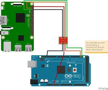
I know the bus is working cause I have the Mega and an Arduino Uno talking to each other. Here is my breadboard layout showing just the Mega and the PI:
RPI 3 to Logic Converter
3.3v (Pin1) <-> LV
SDA (Pin3) <-> LV1
SCL (Pin 5) <-> LV2
GND (Pin 6) <-> GND
MEGA to Logic Converter
5V <-> HV
SDA (Pin 20) <-> HV1
SCL (Pin 21) <-> HV2
GND <-> GND
I have enabled I2C for the RPI as described in the blog (hence why I can run the i2cdetect command at all).
Is this connected correctly? Any ideas? I'd be happy to provide test code if needed. Thanks!!!
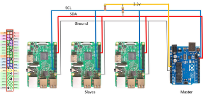
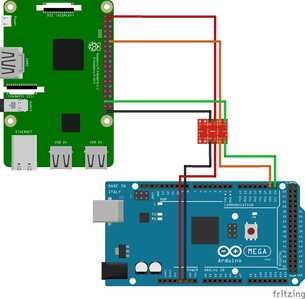
So I haven't gotten any replies, but to keep folks updated here's the latest in my research... It seems that perhaps the PI's GPIO02 and GPIO03 pins commonly used for I2C for master mode are NOT the ones you use for slave mode(?). I found this forum post that suggests using the pigpio library along with pins GPIO18 (SDA) and GPIO19 (SCL) in I2C mode. Here's the diagram they have posted (using the UNO rather than a Mega, but Pi setup would be similar).
I'd assume I could also use a logic converter as before rather than connecting to the Arduino's 3.3v. I also noticed the pullup resistors. The RPI has internal pull-up resistors (as described in the DroneBot blog) for the standard I2C lines (used for master mode). I'm assuming this is NOT the case for other GPIO pins. I'd need to determine what resistance of pullup resistors to use (looks like their pic uses 47k I believe). I'm doing my homework on pullup/pulldown resistors now.
Once I do I think I'm going to try recreating this code from another forum post.
On the Pi3:
#!/usr/bin/env python

import time
import pigpio

I2C_ADDR=9

def i2c(id, tick):
   global pi

   s, b, d = pi.bsc_i2c(I2C_ADDR)

   if b:

     print(d[:-1])

pi = pigpio.pi()

if not pi.connected:
    exit()

# Respond to BSC slave activity

e = pi.event_callback(pigpio.EVENT_BSC, i2c)

pi.bsc_i2c(I2C_ADDR) # Configure BSC as I2C slave

time.sleep(600)

e.cancel()

pi.bsc_i2c(0) # Disable BSC peripheral

pi.stop()
On the Arduino Mega:
// This example code is in the public domain.


#include

void setup()
{
   Wire.begin(); // join i2c bus as master
}

char str[17];

int x = 0;

void loop()
{
   sprintf(str, "Message %7d\n", x);
   if (++x > 9999999) x=0;

   Wire.beginTransmission(9); // transmit to device #9
   Wire.write(str);           // sends 16 bytes
   Wire.endTransmission();    // stop transmitting

   delay(50);
}
Am I making this too difficult? Seems like there should be an easier way, but maybe not. Cheers!
Ok, so I got it (partly) working!
I basically hooked everything up as described for the GPIO 18 & GPIO 19 with the logic converter and no pullup resistors.
I removed all the other slave devices out of the equation too. I made one slight adjustment to the python code to decode the string being sent over. Basically it was literally printing out
bytearray(b'Message 1')
bytearray(b'Message 2')
...
I changed it from
print(d[:-1])
to
print(d[:-1].decode())
which cleared it up. So I proved that I can get messages being sent from the Arduino Mega (master) to the Pi3 (slave) using I2C. Next step will be to integrate it now with my previous code and other I2C slave devices (to do something that I actually want it to do - lol).
Wish me luck!


