Hey guys, I am a little stumped in regards to pin connections when going from using an Arduino Uno board to just using the ATMega328 DIP as described in the Dronebot video. I have some questions...
1. Where do I connect the SCL and SDA wires for my I2C sensors?
2. Do I need to supply 5v power to both VCC connections and connect both GND pins to ground?
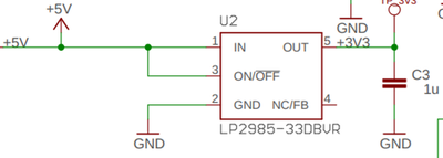
3. Is the 3.3v VCC connection on an UNO generated separately from the ATMega328 chip?
I need to use 3.3v for my two MLX90614 sensors and I already have a regulated 5vdc supply to power the 328. Do I just need a second dc supply to provide the 3.3v?
Thanks! I am learning a lot from you kind folks.
Is this what you need for pinouts?
https://components101.com/microcontrollers/atmega328p-pinout-features-datasheet
1) SCL = A5, SDA=A4
2) GND for sure, VCC probably
3) separate regulator, not part of the ATMega
Anything seems possible when you don't know what you're talking about.
Thanks. I'm not sure why, but other pinouts that I found Googling it did not look right to me. This one is more clear. Again, not sure why, but who knows what my 55 year old brain is doing these days.
2. Do I need to supply 5v power to both VCC connections and connect both GND pins to ground?
Yes for both. Here is the hookup slide from Bills website article. I am including the pins so it's easier to see. 8 and 22 are ground and 7 and 20 is VCC and AVCC.


1. Where do I connect the SCL and SDA wires for my I2C sensors?
Pin 27 SCL and 28 SDA. That slide should be useful. On that article, he does have a slide that is relabeled with equivalent function that might be useful but only use it as a reference only. It will have things labeled like Digital Pin XX and so on to make it easier to program it like an Uno. It can be confusing if you are searching for something that isn't listed there. I will include that one at the bottom.
3. Is the 3.3v VCC connection on an UNO generated separately from the ATMega328 chip?
As Will stated, it is not on the chip so you would have to build your own. In an Uno, it runs 5V through a LP2985-33DBVR but you have many options here. Any 5V to 3.3V regulator will work. Many are cheap on Digikey and some don't have a minimum order. In the Uno it's just the IC and a cap.

So this confuses me...I need to connect my two MLX90614 sensors to the SDA (pin27) and SCL (pin 28) and my OLED display uses Digital pin 13 for the CLK pin. Am I correct in assuming that CLK and SCL both utilize the same clock function and just get connected to the same pin?
Also, what happens if I needed to use the Analog input pin 5? How does the Uno board deal with these pins on the DIP having multiple functions?
Pin 13 is usually the CLK pin for SPI which is a totally separate bus and is not related to the I2C's SCL pin. The CLK used for each are totally independent. Do NOT used the same pin for both.
You cannot use pin A5 if you are using the hardware I2C interface, choose another pin or choose a different interface than I2C.
You can, however "bit-bang" I2C communications using other libraries (than Wire.h). For example take a look at:
Anything seems possible when you don't know what you're talking about.
my OLED display uses Digital pin 13 for the CLK pin.
As Will stated, they are different functions but pin 13 on an Uno would be pin 19 on the DIP package. There should be no conflict.
18 would be MISO and 17 would be MOSI(typo in Bill's slide). You would still keep everything the same in your sketch.
If it worked on an Uno, it should work on the DIP package. Most of the pins are just routed out on the PCB. If you look at the pinout of the UNO and compare it to the pinout of the DIP package, you can see the equivalent connections.
If you are using the ADC, it is recommended that you do some filtering on the AVCC to prevent noise. Here is what the ATMega 328P Datasheet states:
"AVCC is the supply voltage pin for the A/D Converter, PC3:0, and ADC7:6. It should be externally
connected to VCC, even if the ADC is not used. If the ADC is used, it should be connected to VCC
through a low-pass filter. Note that PC6..4 use digital supply voltage, VCC."

