Can you attach the actual circuit you are using?
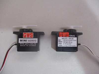
I have two GWS MINI Servos see attached I thought I could use to duplicate your circuit.
I still see no reason to keep attaching the servos in the void loop?
Even if frogandtoad resolves the issues I would still be interested in duplicating it with actual hardware.
Right click on image and choose open link in new window to better read the specs on the servos.
Ok, here are my findings...
Firstly, I wasn't able to find my other sg90, so I had to settle with one servo, however, that worked perfectly, including the print statements - I only had some very slight overshoot on one of the angles, then quickly found it's position and came to a stop - I wouldn't expect more than that from such a cheap servo 🙂
Unfortunately, I wasn't able to find my other sg90 to test with 2 servo's!
Having said that, I did do some further research, and I found many people complaining about this jitter too. There appears to be reports of the Serial interface interfering with the Servo PWM timers, so you could try it without any serial declarations in your code at all, including in setup() to see if that helps.
Some suggestions were to turn off and on interrupts, such as the following, to try and avoid any conflicts:
noInterrupts();
  // critical, time-sensitive code here
  leftEyeLid.write(angle1);
interrupts();
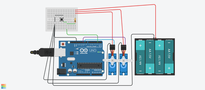
Tinkercad has a pretty neat circuit thingy. I can import actual code, and it seems to respond sorta like real life. And to make it neater, I could invite people to share in it (if I had your email)
I can't figure out how to press the button in the simulation tho
Also, they don't have an arduino nano, so I used an Uno
But I can still show you the circuit. The simulation moves the servos in sync, until it gets to an open, then it jitters just like real life
I was busy typing, so I didn't see your post
I'm trying to make a video of the tinkercad circuit in action. I've never done this before so there's a slight learning curve with 2 brand new (to me) pieces of software
Gimme a minute, I've almost got it
Oh, and I think I do have an Uno in a package I just got from Amazon, might be the mega tho, gotta check
I'll get to your program updates as soon as I finish the video
I think I got both the tinkercad and bandicam playing well together, so here's the simulation video
It doesn't stutter the same way mine does, and I can't figure out how to press the button in the sim
And the amazon package has both an Uno and a Mega, so I can test it on the Uno (after I try your code updates) although, I'm not sure if I have enough space in the helmet for an uno even if it does work, but I'll give it a try anyway if the code update doesn't work
Adding the #define interrupts to the 2nd code seems to have made a world of difference !
I tried tweaking the debounce, and it's not seeming to change anything, but the amount of time I press the button does seem to make a difference. BUT, once I get it actually installed, I'm planning to use a magnetic reed switch, so a quick swipe with a magnet will be easier than a push button that I'm precariously holding and pressing at the same time for as short a period of time as I can while actually holding and pressing it
On the 3rd code, well, nothing I've done seems to have had any positive effect, and adding the noInterrupts() seems to break it. Obviously I'm using it wrong
I think it's working well enough that I'm going to try physically installing it in the helmet, for which I expect to have LOADS of fun working out the angles for the hinges and where exactly to mount them in order to get the thing to open and close without bumping into anything
Due to the way the faceplate is shaped, I'm going to have to use 4 hinges, the 2 on the servos, and 2 others lower down so it pops OUT, and THEN up, otherwise it'll get caught in the helmet part and never move
Moving away from the computer, and down to the workshop...
Preliminary testing with only one servo (cuz you mentioned it might help)
Had to modify a few mounts and use a bigger servo (to handle the load of what should be 2) and I haven't mounted the second set of hinges or adjusted the angles yet. Opens fine, but I need to shut it down sooner on the close cuz the motors keep trying to make it close more, and, honestly, I'm not sure if I need to adjust the open or close since I'm only using the one servo and I just picked a set of wires to plug it into, I didn't really pay attention to if it was 9 or 10
Unfortunately, I had to bring the whole kit and kaboodle upstairs to my computer to adjust the code, so I really have no place to set it down.
I need a new computer for the workshop
Still, all things considered, it's coming along 😉
Your video seems to imply the servos are not for blinking eyes but instead raising and lowering the helmet's visor?
Yes. The first video was to show what I had already gotten done. That the lights work, and I think they look pretty snazzy. Sorry for the confusion
And your Tinkercad seems to imply you are using the same power source for both Arduino and Servos.
No. The nano (it's actually a nano, not an uno. Tinkercad didn't have a nano in their library) is being powered thru the usb port, so, separate power source for each. They only share a negative. Their library does include those usb plugs tho, so I included that to indicate where the nano power was coming from. The tinkercad video should show the plug being plugged in before the circuit starts to work
Note the debounce code I used included the onboard LED but you could remove those lines.
Right now I've got the eyes on a separate circuit from the faceplate. I had intended to only use them as a display cuz it's not easy to see thru them when they're on. I was watching the onboard LED to indicate when the nano was actually reading the button. Leaving it in is fine
I left the helmet in the shop to work out the length of the hinge arms and where to mount the axis for them, which is trial and error (mostly error) but I brought the circuit back upstairs to continue to play with it. Right now it's being powered by only one servo (an MG995) which I was testing cuz @frogandtoad said his circuit was working with only 1 servo, so I figured I'd try that, but I don't really like the way it swings with only one servo, so I'm continuing to test the 2 servo circuit upstairs on my computer, so testing your code is next on the list
so testing your code is next on the list
And it is also important to understand the code so you can write your own code.
And it is also important to understand the code so you can write your own code.
I do slightly better (slightly) with python, that's why my robots use Pi's and Jetsons rather than arduinos
Hardware is easier to manipulate to my needs. Bend, solder, hammer 3d print, force it to my will or imagination, programs don't abide by wishes. They have extremely strict rules, especially arduinos, python is slightly more forgiving, or, at least understandable (to me anyway)
I do pick things up along the way, and I try it myself before I ask for help, but, once I realize I'm in over my head or hit a problem that google can't or won't answer, I reach out
I can't just read a book, I have to learn by doing. I have to solve a specific problem to understand the solution so I understand why the solution works. Like the pullup resistor. I'd seen Bill using it, but didn't understand it until I didn't use one, then understood WHY it was needed. When @frogandtoad mentioned "floating pin" I stopped and googled it so I could understand it better, and then I installed the pullup resistor. You couldn't just tell me to use it, I needed to understand it
All the code that you guys have given me, when it didn't work right, I tried changing things to see if I could figure out what each change did. That's how I learn, change an X or a Y or a comma. Some things I can learn from reading, programming doesn't seem to be one of them
It's not for lack of trying, it's just that, for me, understanding needs a different path from most people
That code works PERFECTLY !
No stuttering or hesitation at all
Thank You !
I'm still playing with the hinge angles and locations and printing new lengths, and now I'm going to have to swap out the single for the double that I actually wanted cuz the single made it a tad lopsided
So far the perfect swing seems to be 35 and 165, so I was pretty close on my guestimate on that part. Of course, once I get the positions and lengths figured out, that could change, but it seems right for clearance so far
Update on the helmet...
The angles (using the current lengths of the arms) turned out to be 120 and 45, which would obviously change if I alter the length of the arms, but I found 4 hinge points that worked, and I was unwilling to do further calculations
In hindsight, I would have been better off with shorter top arms, because the length put too much stress on those tiny servos to make the faceplate swing fast enough, so I swapped out the pair of smaller servos and went back to the single larger one (again), braced the arms so they wouldn't move lopsided, and that part's done and working quite well (Thank You very much @frogandtoad and @robotbuilder)
Next step is adding 2 more servos for the actual eyeLEDs, for which I should be able to use the same code over again. While you CAN see thru the eyeLEDs, you can't see WELL (especially when they're turned ON), so flipping them up (or down, we'll see) out of the way is the best option.
The bluetooth headset is installed and working phenomenally, and when linked to Alexa, she sounds just like a man with a REALLY deep voice. Unfortunately, she can't hear me unless the faceplate is open. Would be neat if I could somehow link Alexa to the faceplate for which I'm sure there's a way, but haven't started investigating it yet. Edge would be preferable to IoT
And it still needs paint of course. Might stay with black, but, still needs paint for gloss
Anyway, I'll post pix when I get further along with it


