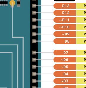
@darksplat Sorry never heard of iBus. Most boards have some PWM many have lots. The UNO has 6 PWM channels, pins 3, 5, 6, 9, 10, 11. They are used with the analogWrite() function. PWM is denoted by the ~ symbol in the pic attached
First computer 1959. Retired from my own computer company 2004.
Hardware - Expert in 1401, and 360, fairly knowledge in PC plus numerous MPU's and MCU's
Major Languages - Machine language, 360 Macro Assembler, Intel Assembler, PL/I and PL1, Pascal, Basic, C plus numerous job control and scripting languages.
Sure you can learn to be a programmer, it will take the same amount of time for me to learn to be a Doctor.
@zander if that is the case then what is the code for the PWM version in the video? Can @dronebot-workshop post a PWM version? I only need 3 PWM signals as that is all that is left on the board from other functions.
@zander iBus/sBus is a protocol that the RC Brands use in there more expresnsive units that puts all of their signals on one wire as per this page
Most actually use PPM these days as it is easy and more acceptable.
- PWM (universal)
- PPM or CPPM (universal)
- SBUS (Futaba, Frsky)
- IBUS (Flysky)
- XBUS (JR)
- MSP (Multiwii)
- CRSF (TBS Crossfire)
- SPEKTRUM1024 (Spektrum DSM2)
- SPEKTRUM2048 (Spektrum DSMX)
- FPort (Frsky)
- SPI_RX (universal)
@darksplat Sorry, I don't really understand what it is you want. I looked at the DBWS blog you provided the link to and it has PWM covered. Perhaps if you could post a sketch you want to convert to PWM and detail how many PWM channels you need and what each should do and what controls each one then maybe someone can help but just hoping Bill (DBWS) has enough spare time to cater to your needs is probably a bridge too far.
First computer 1959. Retired from my own computer company 2004.
Hardware - Expert in 1401, and 360, fairly knowledge in PC plus numerous MPU's and MCU's
Major Languages - Machine language, 360 Macro Assembler, Intel Assembler, PL/I and PL1, Pascal, Basic, C plus numerous job control and scripting languages.
Sure you can learn to be a programmer, it will take the same amount of time for me to learn to be a Doctor.
@darksplat What does the following mean?
We did get it working via bluetooth but that is not what the task has asked for it wants it done via PWM
so our bluetooth code looks like this
I hope I don't sound hash just trying to convoy what we are after a very
It sounds like this is team. Is this for school or something?
First computer 1959. Retired from my own computer company 2004.
Hardware - Expert in 1401, and 360, fairly knowledge in PC plus numerous MPU's and MCU's
Major Languages - Machine language, 360 Macro Assembler, Intel Assembler, PL/I and PL1, Pascal, Basic, C plus numerous job control and scripting languages.
Sure you can learn to be a programmer, it will take the same amount of time for me to learn to be a Doctor.
@darksplat Cool. Your answer earlier confused me though, I gave you the answer and you acted like I didn't tell you. Now that I see the sketch, what I would do is simply replace the digitalWrite with analogWrite. Here is the arduino documentation
https://www.arduino.cc/reference/en/language/functions/analog-io/analogwrite/
First computer 1959. Retired from my own computer company 2004.
Hardware - Expert in 1401, and 360, fairly knowledge in PC plus numerous MPU's and MCU's
Major Languages - Machine language, 360 Macro Assembler, Intel Assembler, PL/I and PL1, Pascal, Basic, C plus numerous job control and scripting languages.
Sure you can learn to be a programmer, it will take the same amount of time for me to learn to be a Doctor.
@darksplat You may find the following article (video as well) instructive.
First computer 1959. Retired from my own computer company 2004.
Hardware - Expert in 1401, and 360, fairly knowledge in PC plus numerous MPU's and MCU's
Major Languages - Machine language, 360 Macro Assembler, Intel Assembler, PL/I and PL1, Pascal, Basic, C plus numerous job control and scripting languages.
Sure you can learn to be a programmer, it will take the same amount of time for me to learn to be a Doctor.
@zander It doesn't have PWM covered in the sense that you can control the robot with PWM, he does have a sketch to test PWM coming from your transceiver and that works fine, but doesn't have a sketch that includes controlling your robot with PWM, he only uses iBus/sBus. Does that make more sense?
Since you say that you're able to see the PWM signal sent from your transmitter on your Arduino and since you say you have a working sketch that uses Bluetooth, i don't really understand your problem.
It seems that all you'd need to do is read in the three remaining channels from your transmitter using PWM channel interpretation as described in Bill's sketch (as you have successfully read it already) and use those three channels' signals to invoke the associated code in your sketch.
From the code you posted, you're not using PWM to the LN298 anyway so your existing code for the different directives for Bluetooth should be completely compatible with the signals decoded from the PWM channel data. You'll just have to interpret the signals to extract left/right/forward/back equivalents from the raw values sent.
Anything seems possible when you don't know what you're talking about.

