Notifications
Clear all

DIY Powerbank for less than 5$

9 Posts
4 Users
2 Likes
3,964 Views
wintech
(@wintech)
Member
Joined: 5 years ago
Posts: 32
Topic starter  

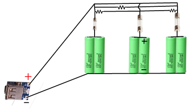
I had made a powerbank for around 1,55$.I used 3 3A fuses,3 10 ohm resistors ,power bank module and a lot of electrical tape.The enclosure is made out of wood.The electronic part is very easy because is all modular.

DSC00008


Quote
hstaam
(@hstaam)
Mr.
Joined: 5 years ago
Posts: 61
 

If I understand correctly you are using 3 pairs of parallel cells. Why the 10 R resistors?. I also do not understand the placement of the 3A fuses in the schematic. They seem to be shorting the cells.

hj

hj


ReplyQuote
Robo Pi
(@robo-pi)
Robotics Engineer
Joined: 5 years ago
Posts: 1669
 
Posted by: @hstaam

I also do not understand the placement of the 3A fuses in the schematic. They seem to be shorting the cells.

I don't think the fuses are shorting the cells.   But they do seem to be only protecting half of the batteries.

Shouldn't the fuses be in series with the 10 ohm resistors?

DroneBot Workshop Robotics Engineer
James


wintech reacted
ReplyQuote
wintech
(@wintech)
Member
Joined: 5 years ago
Posts: 32
Topic starter  

@robo-pi

Well I've messed up the diagram.The 3 resistors should connect to the + terminal like that:Battery pack 1 to battery pack 2 ,battery pack 3 to battery pack 2 and battery pack 1 to battery pack 3.


ReplyQuote
Robo Pi
(@robo-pi)
Robotics Engineer
Joined: 5 years ago
Posts: 1669
 

@wintech,

Sounds like it's time to draw up a new diagram. ? 

The way you currently have it drawn up half your batteries have no fuse protection.

DroneBot Workshop Robotics Engineer
James

   
wintech reacted
ReplyQuote
wintech
(@wintech)
Member
Joined: 5 years ago
Posts: 32
Topic starter  

@robo-pi

Thanks for showing me the problem in the diagram! ? 


ReplyQuote
wintech
(@wintech)
Member
Joined: 5 years ago
Posts: 32
Topic starter  
Untitled

Here is the updated schematic.


ReplyQuote
ETinkerer
(@etinkerer)
Member
Joined: 5 years ago
Posts: 44
 

Swing and a miss. Strike 2. ? 

Not sure what your doing with the resistors now. 

Pat

The most exciting phrase to hear in science, the one that heralds new discoveries, is not “Eureka!” (I found it!) but “That's funny …”
Author: Isaac Asimov


ReplyQuote
Robo Pi
(@robo-pi)
Robotics Engineer
Joined: 5 years ago
Posts: 1669
 

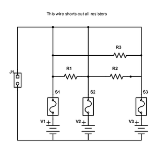
The fuses look better.   But I don't understand the purpose of the resistors now.  In fact, aren't all of those resisters basically shorted out directly by the top most wire in your diagram?

I mean, based on how it appears the resistors won't hurt anything being there, but it also appears that if you take them out it won't make any difference at all.

Can you explain the purpose of these resistors?   What are they supposed to be doing?

Here's what I'm seeing:

schemeit project

DroneBot Workshop Robotics Engineer
James

   
ReplyQuote