@robotbuilder @Inq FYI I am 99% sure I helped somebody with some MPU6050 problems. There were some library issues and something else. If you go down that path, I will search the forum to refresh my memory.
I have several of these GY-89 that do 10 DOF... enough to do Jr. But I was thinking I don't need the Mag part and had picked some 6050's to use on the Inqling, the 3rd next time since they're significantly cheaper. The specs seemed to be as good... mainly rate and 16bit resolution.
Do you remember how long ago? Do you think they've fixed the library?
VBR,
Inq
3 lines of code = InqPortal = Complete IoT, App, Web Server w/ GUI Admin Client, WiFi Manager, Drag & Drop File Manager, OTA, Performance Metrics, Web Socket Comms, Easy App API, All running on ESP8266...
Even usable on ESP-01S - Quickest Start Guide
@inq I have trouble remembering what I had for breakfast. The library issue wasn't a typical broken, just a strange packaging. Let me do a search now.
First computer 1959. Retired from my own computer company 2004.
Hardware - Expert in 1401, and 360, fairly knowledge in PC plus numerous MPU's and MCU's
Major Languages - Machine language, 360 Macro Assembler, Intel Assembler, PL/I and PL1, Pascal, Basic, C plus numerous job control and scripting languages.
My personal scorecard is now 1 PC hardware fix (circa 1982), 1 open source fix (at age 82), and 2 zero day bugs in a major OS.
@inq Try the following two links
https://forum.dronebotworkshop.com/postid/29760/ Most of the changes
https://forum.dronebotworkshop.com/postid/29776/ The last bit
IIRC, the MPU6050 has been superceded by a new 9 axis device. Not sure of name
Here it is https://www.adafruit.com/product/2472
First computer 1959. Retired from my own computer company 2004.
Hardware - Expert in 1401, and 360, fairly knowledge in PC plus numerous MPU's and MCU's
Major Languages - Machine language, 360 Macro Assembler, Intel Assembler, PL/I and PL1, Pascal, Basic, C plus numerous job control and scripting languages.
My personal scorecard is now 1 PC hardware fix (circa 1982), 1 open source fix (at age 82), and 2 zero day bugs in a major OS.
@inq I have trouble remembering what I had for breakfast. The library issue wasn't a typical broken, just a strange packaging. Let me do a search now.
😆 Although, I'm a relative youngster, I can't remember if I had breakfast.
3 lines of code = InqPortal = Complete IoT, App, Web Server w/ GUI Admin Client, WiFi Manager, Drag & Drop File Manager, OTA, Performance Metrics, Web Socket Comms, Easy App API, All running on ESP8266...
Even usable on ESP-01S - Quickest Start Guide
UPDATE
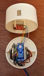
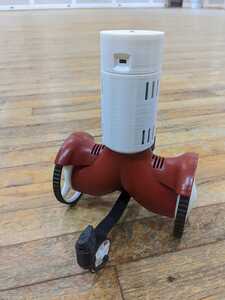
New, independent head unit using servo. Only good for +/- 60 degrees, but we'll live with it in this bot. All DC-to-DC power convert, ESP8266, Gyro, Accelerometer, Magnetometer and ToF sensors are all self contained so only power and optionally serial communications need to be routed up from the bottom unit.
3 lines of code = InqPortal = Complete IoT, App, Web Server w/ GUI Admin Client, WiFi Manager, Drag & Drop File Manager, OTA, Performance Metrics, Web Socket Comms, Easy App API, All running on ESP8266...
Even usable on ESP-01S - Quickest Start Guide
UPDATE
I wanted to do a first-principles stepper motor driver using the hardware timer... mainly just because I wanted to, but I wanted some features that aren't in the Stepper or FastAccelStepper libraries. Mainly...
- Synchronized - I wanted there to be a very tight linking of the two motors so that synchronizing between the two was microsecond accurate.
- Smooth Acceleration - I know FastAccelStepper does accelerations (the name tells me that.. Dah!) but I've never used it and don't have a clue if what I have is as good. The accelerations are critical to reduce slippage. Just banging from one speed to another is a certain recipe to introduce error.
- Transactions - I wanted to be able to load transactions of movements (a choreography if you will) and have it do the calculations of making smooth transitions from one speed to another or to smoothly accel/decel the wheels independently so as to make smooth coordinated turns. It will make the AI controlling the travels easier.
- 2D Dead-Reckoning - I want to do the micro-second and micro-stepping accuracy of the steppers to keep track at the lowest level so I don't have to mess with it up in the AI regions.
- Speed - Although I don't need anywhere near the speed I've been able to Inq out of these Nema-17 motors, I do want more than I've seen in most hobbyist level robots. I want it to easily keep up with me. I don't want to walk at its pase. Now it will out run me, even in a sprint. Not that I sprint anymore. That would be flat out comical. 😆
More on speed - In my first experiences with stepper motors, I tested them by simply setting the speed and seeing if they accepted it. I'd send a new speed and let it jump to the new speed. When at last it couldn't make the jump, I found that I couldn't go below 900 useconds per step. Doing all the Math, it said the bot might make it to 4 mph. However, this was purely turning a wheel in the air. On the ground having to accelerate the bot too, slowed it down. Once I started working with this new driver, I noted the 900 uSecond limitation went away. Now it is purely a matter of accelerating at a slow enough rate to not cause the steppers to give up. Give me a Kansas highway, and watch out. In free air, the steppers were able to turn the wheel up to 36 mph. If I can get 5 mph on the ground, that'll be good enough.
The following posts will be baby-step boring videos of the calibrating process. I doubt there will be much dialog, but I'll supplement it in the posting so you don't have to be bored to tears watching the video.
VBR,
Inq
3 lines of code = InqPortal = Complete IoT, App, Web Server w/ GUI Admin Client, WiFi Manager, Drag & Drop File Manager, OTA, Performance Metrics, Web Socket Comms, Easy App API, All running on ESP8266...
Even usable on ESP-01S - Quickest Start Guide
Although I don't need anywhere near the speed I've been able to Inq out of these Nema-17 motors, I do want more than I've seen in most hobbyist level robots.
You have the need for speed 🙂
Will it will stop in time before it tumbles down the stairs or crashes into a wall 🙂
Will it have the time to process all that TOF data to make split second decisions as to what to do next?
Stay tuned ... 🙂
Speed's just for keeping up with me. I hope to add a follow-me mode. For moving around and especially mapping, I'd say it'll be a LOT slower. But you bring up some valid points and I do plan on doing the maximum acceleration (thus deceleration) also and have the halt button. I'm imagining a top speed will be based on the deceleration distance being less than the reliable ToF sensor range. Stay tuned ... 🙂 agreed.
3 lines of code = InqPortal = Complete IoT, App, Web Server w/ GUI Admin Client, WiFi Manager, Drag & Drop File Manager, OTA, Performance Metrics, Web Socket Comms, Easy App API, All running on ESP8266...
Even usable on ESP-01S - Quickest Start Guide
First Try
This is the first cut that I had ready to publish on Saturday, but I had several issues to iron-out besides the ones obvious in the video. Applying calibration factors was simply not working as I was expecting. It wasn't till I was home later that I realized what might be the problem.
6. There is a sixth feature of the library, that I forgot about. Because I expect Inqling Jr to spend a lot of time sitting still and doing calculations, I wanted to reduce the sizable power draw A4988 stepper motor drivers use even when sitting still. Other drivers I'll be exploring won't have this issue. Anyway, I made my software drivers detect when both motors were still and disable/enable the A4988 drivers transparently. (why I forgot about it) This allows me many hours on a charge especially as I iteratively design, code and debug them.
Unfortunately, I have a theory, that the micro-seconds I start pulsing the motors from a dead stop are too quick and the A4988, being just enabled hasn't had enough time to boot if it has such a thing. I'll be exploring that today and have more videos, but here's Saturday's video.
3 lines of code = InqPortal = Complete IoT, App, Web Server w/ GUI Admin Client, WiFi Manager, Drag & Drop File Manager, OTA, Performance Metrics, Web Socket Comms, Easy App API, All running on ESP8266...
Even usable on ESP-01S - Quickest Start Guide
In this Take 2, I've manually enabled the stepper motor drivers.
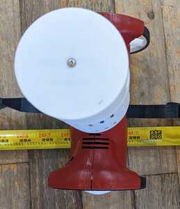
To calibrate for distance:
- Distance told to travel 7.6 meters
- Distance actually traveled 298.68" => 7.5865 meters (~0.2% error)
- Estimated wheel diameters used for Run = 0.0985 meters
- Resized wheel diameters for Run 2 = 0.0985 * 7.5865 / 7.6 = 0.098325 meters.
Calling that at 299 and 5/16ths => 7.6025 meters
Versus 7.6 meters => 0.033% error.
I think it's fair to say, that the A4988 Stepper Motor Drivers do have a small, but significant boot-up phase. Having them already on before starting the run definitely made the run data make sense and lead to more accurate diameter readings than could be achieved with calipers.
Next Up - Calibrating the track width.
3 lines of code = InqPortal = Complete IoT, App, Web Server w/ GUI Admin Client, WiFi Manager, Drag & Drop File Manager, OTA, Performance Metrics, Web Socket Comms, Easy App API, All running on ESP8266...
Even usable on ESP-01S - Quickest Start Guide
Calibrating the track width property is very important as all calculations for dead-reckoning angle changes are based on the diameters of the two wheels as they rotate differently and the track width. The common practice is to measure the distance to the center of the contact patch of the two tires. For Inqling Jr the first ruler based measurement is using this concept.
- Initial track width measurement = 0.15 meters
The Calibration Procedure
In this first demonstration of the procedure, the angle was a little over 10 degrees shy of making the full 360 degrees. The percent error is 2.8% at this point before calibration. Since the angle is linear with respect to the track width, the track width error is also around 2.8%.
Just to make things even more accurate, I decided to make Inqling Jr dizzy and turn it around ten times for 3600 degrees. In the second test, I could easily just set up the ratio of error and approximate a better "guess". After that it was more of a trial and error as I got closer and closer to a good value.
Here are the results:
https://youtube.com/shorts/Thgtg9J2sDE?feature=share
After turning 3600 degrees, it overshoots by less than 0.5 degrees.
Final track width = 0.1546 meters
Final evaluation = 0.014% error.
Next Up - Calibrating the difference in wheel diameters.
3 lines of code = InqPortal = Complete IoT, App, Web Server w/ GUI Admin Client, WiFi Manager, Drag & Drop File Manager, OTA, Performance Metrics, Web Socket Comms, Easy App API, All running on ESP8266...
Even usable on ESP-01S - Quickest Start Guide
Even though they're printed on the same 3D Printer there are a slight difference in wheel diameters/circumferences. If we can safely assume that our distances and angle changes are now calibrated accurately, we can now attempt to correct for these very small differences in wheel diameter.
To do that, we set up a choreograph of movement segments to accentuate this bad behavior. We use 8 segments.
- Accel for X meters
- Travel at constant speed for 2*X meters
- Decel for X meters to come to a complete stop.
- 180 degree turn
- Accel for X meters
- Travel at constant speed for 2*X meters
- Decel for X meters to come to a complete stop.
- 180 degree turn
Once everything is all calibrated, it should be pointing at the same location as when it left. This is using the wheel calibrations from the distance calibration steps above.
- Left wheel = 0.098325 meters
- Right wheel = 0.098325 meters
The following is using:
- Left wheel = 0.098345 meters
- Right wheel = 0.098200 meters
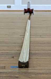
Although, this result is pretty good, watching it bounce around on the wood floor is convincing me this might be a problem. The hallway floor has a 80 foot section of linoleum that looks to be smoother.
More boring videos to come!
VBR,
Inq
3 lines of code = InqPortal = Complete IoT, App, Web Server w/ GUI Admin Client, WiFi Manager, Drag & Drop File Manager, OTA, Performance Metrics, Web Socket Comms, Easy App API, All running on ESP8266...
Even usable on ESP-01S - Quickest Start Guide
This was trial 7 and although it wasn't much better on the distance (about 14 inches away), watching it go down the hall... it was nailed to the center line. It almost looked like the 180 degree turn around was the problem and could easily account for the return leg veering. It simply was pointing in the wrong direction.
As all three of these settings (distance, track width and relative wheel diameters) are dependent on each other, I will need to re-do them starting with this more refined set and see if things can be improved. One other thing, the hall-way is longer and I was able to go to 20 meters each way.
- Left wheel = 0.09847 meters
- Right wheel = 0.09818 meters
Interesting that they are even this much different... about 0.3%!
Stay tuned.
VBR,
Inq
3 lines of code = InqPortal = Complete IoT, App, Web Server w/ GUI Admin Client, WiFi Manager, Drag & Drop File Manager, OTA, Performance Metrics, Web Socket Comms, Easy App API, All running on ESP8266...
Even usable on ESP-01S - Quickest Start Guide
Took some time to respond, side tracked by the brushless motors thread resulting in spending time learning about them, and I had to read your posts and watch your videos a few times to soak up your experiments and their results.
It almost looked like the 180 degree turn around was the problem and could easily account for the return leg veering. It simply was pointing in the wrong direction.
That is probably always going to be a source of error for it only has to be out a little bit for the robot to end up missing the target more and more with increased distance even it it travels in a perfect straight line.
I did a lot of odometry experiments to fine tune the calibrations on my robot bases. I have a different heavier robot with different motors and use encoders to count the "steps" taken. Just to get moving I have to hit the motors with a large enough PWM. The other difference is I am using vision to lock the robot onto the environment.
I was wondering with pointing the robot base in a definite direction how accurately that could be done with an electronic compass?
Before GPS people used to use a hand held compass on walking treks. Of course they also used distant landmarks where possible. Maybe it would get your robot close enough to each target that could be recognized by the TOF sensor. Of course the target would have to be a 3d shape as TOF will not recognize a blue dot on the floor or wall or read a traffic sign 🙂
I also noticed more cheap robot vacuum cleaners coming out now using gyroscope navigation to improve their performance. I wonder if that would help supplement encoder data.

