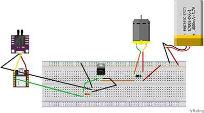
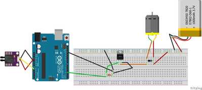
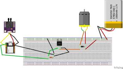
I have a small project that i am working on that involves a Seeed Xiao a potentiometer and lastly a 3 volt DC motor. Very simple setup, so I thought.
I got the 3 pieces working together on a Arduino Uno. However, I am having difficulties switching to the Seeed Xiao. Not sure where my problem is.
I was hoping someone would have a sample code set and wiring diagram already created that i could start from.
Any help would be greatly appreciated
Thank you
Jamie
Bill has done a video of the Xaio, you might like to review it ...
https://dronebotworkshop.com/seeeduino-xiao-intro/
It would also help if you could be more specific about what problem(s) you're having. Just telling us that you're "having difficulties" makes the problem hard for us to diagnose 🙂
Anything seems possible when you don't know what you're talking about.
Thank you will for your reply I really appreciate it. The following is what doesnt work.
Xiao bread board Motor does not run with the following code:
#define fadePin 3
int potIn = A0;
float adc_avg = 0;
int veloc_mean_size = 20;
void setup()
{
// put your setup code here, to run once:
pinMode(fadePin, OUTPUT);
Serial.begin(9600); // initialize serial communications at 9600 bps
for (int ii = 0; ii < veloc_mean_size; ii++)
{
//adc_avg += analogRead(A0) - offset;
adc_avg += analogRead(A0);
Serial.println(adc_avg);
}
adc_avg /= veloc_mean_size;
}
void loop()
{
adc_avg = analogRead(A0);
Serial.print("Analog reading = ");
Serial.println(adc_avg);
float rad = DEG_TO_RAD * 1;
int sinOut = constrain((sin(rad) * 128) + 128, 0, 255);
//sinOut = sinOut + 125;
Serial.print("sinout = ");
Serial.println(sinOut);
analogWrite(fadePin, sinOut);
if(adc_avg <= 130)
{
sinOut = 0;
analogWrite(fadePin, sinOut);
Serial.print("sinout <= 39 = ");
Serial.println(sinOut);
}
else
{
sinOut = sinOut + 125;
analogWrite(fadePin, sinOut);
Serial.print("sinout = ");
Serial.println(sinOut);
}
delay(2000);
}
This Setup in breadboard does work with the Uno. The following code also works with the image. I used a pressure sensor in both the images and the pressure sensor does drive the DC motor in this sketch.
I can't tell from your wiring diagrams, but I believe that the Xaio numbers pins from zero instead of 1. If you have just duplicated the wiring (pin for pin) you may have inadvertently selected the wrong pin (so it now doesn't match the sketch on the Xaio).
====================== edited later ==============================
The other aspect is whether the 3.3V output from the Xiao is enough to drive the transistor to provide enough power to the motor. It may be worth testing the voltage across the motor.
Anything seems possible when you don't know what you're talking about.
Thanks for the reply Will.
p30n06le MOSFET Gate to threshold voltage minimum 1 max of 2.
Uno pins:
A0 = Analog input
3.3V = VCC - Sensor
Ground = Ground - Sensor
~3 = Output to mosfet gate
Xiao pins:
A0 = Analog output
3.3V = VCC - Sensor
Ground = Ground - Sensor
D3 (0 Based) = Output to mosfet gate
So is digital Uno ~3 the same as D3 on Xiao? Does A0 on the Uno work the same as A0 on Xiao?
Speaking of Mosfet is a mosfet a must if the Pump is 3 volts? just use a diode, is that possible?
Would you recommend a different curcuit?
I'm not sure, I've never used a xiao but I believe that it's supposed to be pretty much comparable with the Arduino.
In your Fritzing diagram for the xiao, it appears that the GND is not connected to the sensor. Is that an error in the diagram or is it really not connected ?
The MOSFET isn't a "must", it could be replaced by a regular power transistor but there's no real point to doing so. The specs for it look good, it will be fully "on" at an available voltage and should handle the load well.
Anything seems possible when you don't know what you're talking about.
In the future, please put your code in using the code editor button.
It would be very helpful making it easier to read. Everyone does it coming in to the forum... me included.
Two thoughts...
- My first thought since the Uno uses 5V pin logic, and the xiao 3.3V was the transistor being fully turned-on. @will knows the hardware far better and says yes. I'll bookmark down this Mosfet for future use with ESP8266/ESP32. Thanks @will.
- Most MPU's besides Arduino (ESP8266/ESP32) have mappings for the logic pins. They don't use 0, 1, 2, 3... etc. They use D0, D1, D2, D3 and they actually map to pins 16,5,7,42 etc. I'm betting you just need to change the line
#define fadePin D3    // <==== Change to this
int potIn = A0;
float adc_avg = 0;
int veloc_mean_size = 20;

void setup()
{
- If that doesn't work, check you xiao and see if the pins have some kind of different mapping.
- If you have one handy, put a LED across your circuit and see if it lights up/dims.
Hardware's not my strong suit, so take with a grain of salt.
VBR,
Inq
3 lines of code = InqPortal = Complete IoT, App, Web Server w/ GUI Admin Client, WiFi Manager, Drag & Drop File Manager, OTA, Performance Metrics, Web Socket Comms, Easy App API, All running on ESP8266...
Even usable on ESP-01S - Quickest Start Guide
Speaking of Mosfet is a mosfet a must if the Pump is 3 volts? just use a diode, is that possible?
Would you recommend a different curcuit?
Oh gosh no! The diode might stop the back EMF. But powering the motor directly from the pin through just a diode would certainly burn out the logic pin. You have to have the Mosfet or a real motor driver board to handle the higher voltage/current needed by motors. The Mosfet is the cheap/easy, the motor drivers just add forward/reverse capability.
A pin might only be able to handle 0.010 amps, while a motor especially one being loaded up driving a pump might pull far more. Anything more than the 10 mA and the pin becomes toast.
I have one of these small motor/pump kits for house plants... I wire it up and see how much it pulls.
VBR,
Inq
3 lines of code = InqPortal = Complete IoT, App, Web Server w/ GUI Admin Client, WiFi Manager, Drag & Drop File Manager, OTA, Performance Metrics, Web Socket Comms, Easy App API, All running on ESP8266...
Even usable on ESP-01S - Quickest Start Guide
The ground is connected to the sensor. With Xiao it’s difficult to diagram cause it only has 1 ground.
40 mA - Running the pump in air.
160 mA - Startup when submerged.
Both will kill most logic pins on MPU. Although Uno are built more robustly.
https://www.amazon.com/WayinTop-Automatic-Irrigation-Watering-Capacitive/dp/B07TLRYGT1/
3 lines of code = InqPortal = Complete IoT, App, Web Server w/ GUI Admin Client, WiFi Manager, Drag & Drop File Manager, OTA, Performance Metrics, Web Socket Comms, Easy App API, All running on ESP8266...
Even usable on ESP-01S - Quickest Start Guide
Hi (@jkoch), and welcome to the forum..
In reference to your fritzing dwg of how you are connected to the Seed xioa, I do not see how you are powering either the pressure sensor (MPXV70020p) or the Seed Xiao from your power source of 3.7 Volts.
In the specifications for the MPXV70020p states the voltage supply is between 4.75~ 5.25 V,
https://www.digikey.com/en/products/detail/nxp-usa-inc/MPXV7002DPT1/1168437?s=N4IgjCBcoLQBxVAYygMwIYBsDOBTANCAPZQDaIArAGwIC6AvvYQExkgCyACgBoBqA7AAZBzACKcAKhAZA and there is no connection shown to power either one. Is this just a drawing mistake? If the MPXV70020p requires the higher voltage( 4.75 -5.25 V) then you would require a voltage level shifter to make it compatible with the 3v Xioa. https://www.amazon.com/MTQY-Channels-Converter-Bi-Directional-Shifter/dp/B09M8CN4FG/ref=sr_1_6?keywords=5V+to+3.3V&qid=1659705098&sr=8-6
The rest of the circuitry looks ok, and should work.
Please keep us informed of your progress,
kind regards,
LouisR
LouisR
Thank you for your reply I really appreciate it.
First thing, The only image in fritzing that i could find was the 7002 that was similar. With that im using a Portal maker XGMP3v3 Sensor ( https://makersportal.com/shop/xgmp3v3-differential-pressure-sensor-for-arduino-and-raspberry-pi). Which is from what i can tell is functioning correctly.
I modified my code (placed in code section) and the in and out pins. See new diagram attached.
Sensor is putting out 1.47 volts (more pressure it increases volage up to 2.74) to the 2 pin. the 0 pin only has .79 volt which will not open the mosfet (p30n06le). So I think im not doing something correct on the out pin...
//#define fadePin 3
//int fadePin 3;
//int potIn = A0;
int Pot = 2; // Sensor
int Pot_Data = 0; //Should be OUTPUT
float adc_avg = 0;
int veloc_mean_size = 20;

void setup()
{
  // put your setup code here, to run once:
  pinMode(Pot_Data, OUTPUT);
  pinMode(Pot, INPUT);
  //pinMode(fadePin, OUTPUT);
  Serial.begin(9600); // initialize serial communications at 9600 bps

  for (int ii = 0; ii < veloc_mean_size; ii++)
    {
        //adc_avg += analogRead(A0) - offset;
        adc_avg += analogRead(2);
        Serial.println(adc_avg);
    }

    adc_avg /= veloc_mean_size;
}

void loop()
{
    adc_avg = analogRead(2);
    Serial.print("Analog reading = ");
    Serial.println(adc_avg);

    float rad = DEG_TO_RAD * 1;
    int sinOut = constrain((sin(rad) * 128) + 128, 0, 255);
    //sinOut = sinOut + 125;

    Serial.print("sinout = ");
    Serial.println(sinOut);
    analogWrite(0, sinOut);

    if(adc_avg <= 130)
    {
      sinOut = 0;
      analogWrite(0, sinOut);
      Serial.print("sinout <= 39 = ");
      Serial.println(sinOut);
    }
    else
    {
      sinOut = sinOut + 125;
      analogWrite(0, sinOut);
      Serial.print("sinout = ");
      Serial.println(sinOut);
    }

    delay(2000);
}
@jkoch May I suggest trying to simplify. Remove the motor, instead insert a LED (watch polarity) to see if the logic is correct. If the LED works, maybe a seperate motor power supply is needed? If the LED does NOT light up, replace the MOSFET gate with a simple battery to test the MOSFET. If the LED does not light up the MOSFET is either bad or the wrong type/spec, if it does light up, then the board is not connected correctly. Try those steps first as the next steps are tedious.
First computer 1959. Retired from my own computer company 2004.
Hardware - Expert in 1401, and 360, fairly knowledge in PC plus numerous MPU's and MCU's
Major Languages - Machine language, 360 Macro Assembler, Intel Assembler, PL/I and PL1, Pascal, Basic, C plus numerous job control and scripting languages.
Sure you can learn to be a programmer, it will take the same amount of time for me to learn to be a Doctor.


