
Notifications
Clear all

Topic starter
2023-02-19 9:01 am
I have moved this here in case you want to continue with the project or anyone else wants to get involved.
it will be a piece of cake for a pro person to replace a variable resistor with a push button but for a beginner like me it might take a month or more to understand the concept of it.
If you are serious about electronics then you have to learn the basic concepts involved first if you want to play with circuits or have some understanding how they work.
A variable resistor is simply a strip of resistive material which you can tap at any point between the two ends. You can find images for this on the internet.
You could have fixed resistors in series and tap them at their connections. The image below illustrates a simple three resistors with two tap points selectable by a switch but you can more resistors and thus more tap points.
Instead of a switch you have an electronic version that can be rotated incrementally with the push of a button.
to enlarge an image, right click image and choose Open link in new window.


najam.ali99 reacted

2023-02-19 12:06 pm
that is very kind of you sir
i have been asked before to repost on an appropriate forum which i couldn’t find,thank you for doing it for me.
i am a beginner but as long as my seriousness about electronics is concerned , i would like to mention that half of my salary is going in to this hobby 😋 & my weekends
i have pretty much everything in my lab except oscilloscope & im willing to get one soon.
it is easy to make a latching circuit with 555 timer
thanks to bill because he made a video about it.
but problem with 555 timer is that current is not enough to run this motor i am working with.it takes 22 to 28 miliamps of current.
if i attach a mosfet with it current shoots up beyond my requirement and button stops working.
that is problem no 1: how to control current
i know ohms law
i know about voltage divider circuit with resistors, which is used in 555 timer aswell
second thing comes to my mind is that transistors or logic gates can be used to switch between different speeds with one push button. if you have any data regarding this please do share with me
point no 2 : how to identify the suitable components of logic ics? where can i get such information, like a bridge rectifier can be made with 4 diodes, later i found a single chip in led bulbs which is compact and does the same job.
there must be an ic for this job , because i have found this same function in different devices.
2023-02-19 2:08 pm
Hi @najam-ali99,
Controlling the speed of a DC motor is usually a bit more tricky than it appears at first sight. Admttedly, (many years ago at least, I am out of date!), children's electric trains and electric slot-cars were controlled by a hand operated rheostat -- variable resistor with a sliding contact over a resistive wire -- but as demonstrated by the slot-cars in particular, it relied heavily on the user compensating for the change of load.
Actively controlling the voltage, usually by some form of Pulse Width Modulation, may provide a better control than a simple resistance, and when implemented correctly, wastes less power as heat.
This forum's generous host Bill @dronebot-workshop, has produced some excellent videos with accompanying notes, on controlling motors, which you may find helpful.
e.g. https://dronebotworkshop.com/transistors-mosfets/
This includes an example of controlling the speed of small DC motor, using a potentiometer to provide a low current voltage signal for the Arduino to measure and the Arduino in turn controlling a MOSFET to handle the current supplied to the motor.
-------
Perhaps slightly more complex than you need for your present aim, but hopefully interesting and informative:
https://dronebotworkshop.com/dc-motor-drivers/
This mainly describes using chips and also some more sophisticated modules, all of which include an H-bridge to enable the motor to be reversed. The simpler chips described basically consist of 4, almost independent, transistors in a package, each transistor being driven by an Arduino generating a PWM drive signal. For motors that do not need to be reversed, the principle is the same, but only one of the four transistors are required.
--------
I am sure we all understand that many people's budgets are limited, and that purchasing in some parts of the world is easier than in others, but in most cases it should be possible to replicate these examples on a fairly modest spend, albeit you may need to do some searching, etc.
Good luck with your hobby - I wish you well. Dave
najam.ali99 reacted
Topic starter
2023-02-19 4:42 pm
A 3.7 volt motor simply means you need to connect the motor to a 3.7 volt power supply and that will result in what ever current the motor requires. The important thing is can the power supply deliver the required current? A motor under load will draw more current than one that is free running.
You mention using logic gates is this what you mean?
https://www.eleccircuit.com/12v-dc-motor-speed-controller-by-4011/
We still come back to the issue of replacing the variable resistor with a push button to control the variable resistance. I would have to experiment with that. I see the required behavior is used in some commercial products but I can't find an example of such a circuit on the internet. I would have thought it would have been of interest to any electronics member of the forum. Easy to do with a microprocessor but is that really how the commercial products work.
Maybe it could be done using the 4017 ic.
By the way I am just a self taught hobbyist and it was a long time ago that I learned the basics. Since then I have mainly been interested in programming as a hobby.

2023-02-19 5:20 pm
@najam-ali99 Your statement about knowing ohm's law is suspect since you said
if i attach a mosfet with it current shoots up beyond my requirement and button stops working.
The current is drawn, not pushed.
Find Bill's video on MOSFET's to learn how to use one. Once you have a MOSFET a 555 IC can provide the various PWM signals needed to achieve your speeds.
Now your challenge is to figure out how to make a simple push button select different PWM speeds. I don't have a canned answer, but I suspect some sort of IC or maybe more than one can be connected to a push button to provide what is needed. I wonder if a 555 can be used as some sort of solid-state rotary switch concept.
The following link can be useful to design these kinds of circuits and it even emulates a scope HERE
Good luck.
First computer 1959. Retired from my own computer company 2004.
Hardware - Expert in 1401, and 360, fairly knowledge in PC plus numerous MPU's and MCU's
Major Languages - Machine language, 360 Macro Assembler, Intel Assembler, PL/I and PL1, Pascal, Basic, C plus numerous job control and scripting languages.
Sure you can learn to be a programmer, it will take the same amount of time for me to learn to be a Doctor.
Topic starter
2023-02-19 11:36 pm
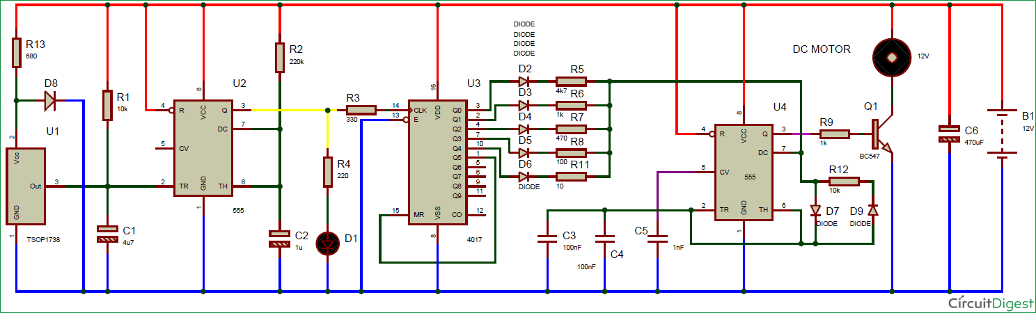
This comes the closest I can find which I think to what I was suggesting where R5,R6,R7 and R11 are acting like the Pot replacement for the 555 and the infrared diode D1 is like a push button ?
https://circuitdigest.com/electronic-circuits/wireless-dc-motor-control-circuit-diagram
I know you probably don't have the expertise to make use of it but perhaps some electronic expert might get involved...
The dimmer lights where you touch them and with each touch they get brighter and then turn off on the fourth touch use a special chip the TT6061. I noticed in its internal circuit it uses a counter and encoder like a surmised as part of the solution.
My guess is you will probably go for the easy software solution using an Arduino board 🙂
Ron reacted
2023-02-20 1:42 am
Hi @robotbuilder ,
Re: Easy to do with a microprocessor but is that really how the commercial products work.
I am not an expert, in the sense that I am not a market researcher who reviews thousands of products, but in my limited scope, then I think the general answer to your question is yes ... microprocessors are extremely widely used.
Perhaps the reason is that cost is largely measured in square mm of silicon ... simple microprocessors can be built on a very small silicon area ... the plastic package probably costs more than the active device, and there are ways of not even having a package .. just solder the silicon directly to the pcb with no package, pins or intenal wiring to do.
Plus the same design can be used in different products with different software .. maybe history repeating itself? Intel is supposed to have 'invented' the microprocessor as a way of supplying one chip design to a calculator manufacturer, who made a range of different models.
The circuits you have found using 555s and so on, are ingenious, but would generally be much more expensive to make in volume than a microcontroller solution. Even 'simple' circuits like buck converters now use microprocessors as the core of their design.
I used a few 555s for a research project in the later 1970s, before microprocessors were generally available in around 1979 ... I wouldn't repeat that approach now!
Best wishes, Dave
Topic starter
2023-02-20 2:56 am
@najam-ali99 FYI
Yes I think you are right. Programming is in a sense wiring up hardware in the processor using code.
Maybe for this simple project it could be done with a cheap ATtiny85, a button switch and a mosfet. The PWM on time could be limited to an equivalent voltage value of the 2.7volt required by the motor at full speed.
https://www.hackster.io/Arnov_Sharma_makes/attiny13a-motor-controller-board-abf84d

2023-03-03 1:26 am
Hi, I know I may be a little late for the party, but found your post for help with controlling a DC motor with a push button using hardware..Although I believe it would be much easier to use a MCP ( micro-controller-processor) like an Arduino uno, rasp-Pi etc..I have a circuit for you to study to see if this is what you are trying to accomplish.
The circuit uses a push button to control the motor as follows:
When power is applied, the motor is at 0 rpm, stopped--
1st button push will start the motor at about 1/3 of it's total rpm for the voltage given.
2nd button push will increase the motor rpm to 2/3 of the total rpm.
3rd button push will increase the motor rpm to full speed.
4th button push stops the motor and will start the sequence all over again with the button is pushed.
The circuit is in 4 section, they are the following,
input section: this consist of the push button labeled SW1, a de-bounce circuit made up of R1,R2,D1, and C1, and an inverted Schmitt-trigger (CD40106).
A Pulse counter circuit: this consist of a dual J-K master flip flop (CD4027).
Summing amplifier: this consist of R3,R4, Op-amp UA741,R5, & R6. This part of the circuit is a poor mans DAC, and converts the digital counts to an analog voltage.
A Pulse PWM generator: This consist of a NE555 timer chip, R&,R8,C2. This will generate the the PWM by controlling pin 5 of the 555 timer.
A motor controller: I used what I had on hand, a L293D controller chip.
and of course, a DC motor, I used a Ch-Ga12-N20-3 , 3-12 volts, @7.4 volts,8200 rpm, gear reduction of 12:1, so shaft speed was ~ 680 rpm.
This can be bread boarded, and works fairly well, although it is not all that linear, and will only give out about 95% duty cycle at full speed setting. But it will be fun to play with to learn how the different parts work to create this circuit.
Here's the circuit layout:

good luck with your project.
LouisR
LouisR